High-frequency current supressor capable of being readily attached to cable or like and earphone system using same
A high-frequency current and suppressor technology, which is applied to the structural components of transient suppressors, transmission systems, telephone structures, etc., and can solve problems such as electronic information equipment failures
- Summary
- Abstract
- Description
- Claims
- Application Information
AI Technical Summary
Problems solved by technology
Method used
Image
Examples
no. 1 example
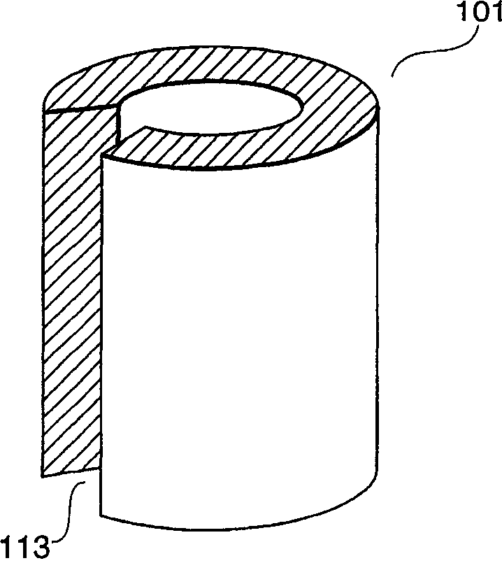
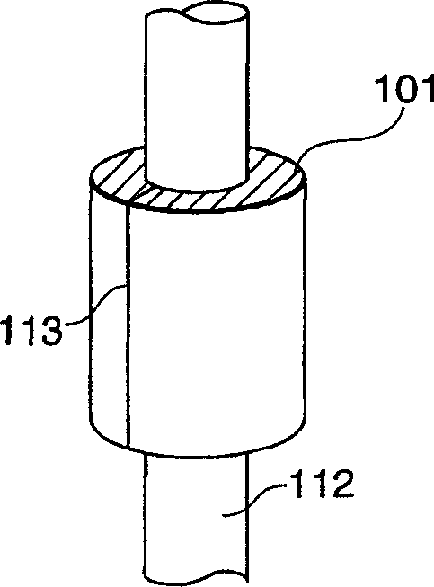
[0045] First, referring to FIG. 1(a) and FIG. 1(b), a high-frequency current suppressor according to a first embodiment of the present invention will be described.
[0046] As shown in FIG. 1(a), the high-frequency current suppressor 101 is substantially composed of a composite magnetic material including soft magnetic powder obtained by flattening an alloy powder including at least Fe, Si, and Al, and a binder material. The composite magnetic material is molded into a cylinder with an inner diameter of 1.5 mm, an outer diameter of 2.65 mm, and a length of 10.0 mm. The composite magnetic material has a split 113 on a portion of the cylinder along its length. Therefore, the molded composite magnetic material has flexibility.
[0047] On the other hand, FIG. 1(b) shows a case where a high-frequency current suppressor 101 made of a composite magnetic material is mounted to a signal cable 112 whose outer diameter dimension is about 1.5 mm. As described above, the high-frequency ...
no. 6 example
[0075] An earphone system according to a sixth embodiment of the present invention will be described with reference to FIG. 7(a) and FIG. 7(b). The structure of the headphone system according to the sixth embodiment is basically the same as that of the headphone system of the fifth embodiment shown in FIG. 6(a) and FIG. 6(b). Therefore, similar parts are denoted by like numerals and not described in detail.
[0076]As shown in FIG. 7( a ), the earphone system 202 includes a high-frequency current suppressor 225 installed in series at one end of the earphone 211 . As shown in FIG. 7( b), the high-frequency current suppressor 225 is formed to have an inner diameter of 1.55 mm, an outer diameter of 3.30 mm at the highest position, an outer diameter of 2.0 mm at the lowest position, and a length of 5.5 mm in a conical portion. Hollow conical. 7(a) and 7(b), in the case where the inner surface of the high-frequency current suppressor 225 is adhered to the outer surface 216a of th...
no. 7 example
[0078] Next, an earphone system according to a seventh embodiment of the present invention will be described with reference to FIG. 8(a) and FIG. 8(b). The structure of the headphone system according to the seventh embodiment is basically the same as that of the headphone system of the fifth embodiment shown in FIG. 6(a) and FIG. 6(b). Similar parts are denoted by like numerals and not described in detail.
[0079] As shown in FIG. 8(a), an earphone system 203 according to a seventh embodiment of the present invention includes a high-frequency current suppressor 235 installed on a signal cable 234 near an earphone 211, which is the same as the fifth embodiment described above. The signal cable 234 is a so-called coaxial cable. The signal cable 234 includes: an inner conductor (not shown); an outer conductor; an insulating coating for insulating the inner conductor from the outer conductor; and a cable insulating jacket for covering the outer conductor substantially along its ...
PUM
| Property | Measurement | Unit |
|---|---|---|
| The inside diameter of | aaaaa | aaaaa |
| Outer diameter | aaaaa | aaaaa |
| Length | aaaaa | aaaaa |
Abstract
Description
Claims
Application Information
 - R&D
- Intellectual Property
- Life Sciences
- Materials
- Tech Scout
- Unparalleled Data Quality
- Higher Quality Content
- 60% Fewer Hallucinations
Browse by: Latest US Patents, China's latest patents, Technical Efficacy Thesaurus, Application Domain, Technology Topic, Popular Technical Reports.
© 2025 PatSnap. All rights reserved.Legal|Privacy policy|Modern Slavery Act Transparency Statement|Sitemap|About US| Contact US: help@patsnap.com


