Electric wave warmer

A heater and radio wave technology, which can be applied to heating appliances for treatment, microwave therapy, and parts of surgical instruments, etc., can solve the problems of noise interference from surrounding electronic machines and high level of radiated noise.

Inactive Publication Date: 2003-12-31
MARUTAKA CO LTD
View PDF0 Cites 0 Cited by
  • Summary
  • Abstract
  • Description
  • Claims
  • Application Information

AI Technical Summary

Problems solved by technology

[0006] However, when using such as image 3 In the case of the coaxial cable of the structure shown, the level of radiation noise from the cables 66, 67, etc. will be high, and peripheral electronic devices such as radios will be disturbed by noise.

Method used


Image

  • Electric wave warmer
  • Electric wave warmer
  • Electric wave warmer

Examples


Embodiment Construction

[0015] Embodiments of the present invention will be described in detail below. Figure 5 It is a block diagram showing the configuration of the electromagnetic wave heater, and the oscillator circuit 52 generates, for example, an AC signal of 27.17 MHz. The amplifying circuit 53 amplifies the AC signal using an amplifying element such as a transistor, and outputs about 40W of power. The filter circuit 54 is, for example, a band-pass filter composed of a coil and a capacitor to pass only a desired frequency (eg, 27.17 MHz).

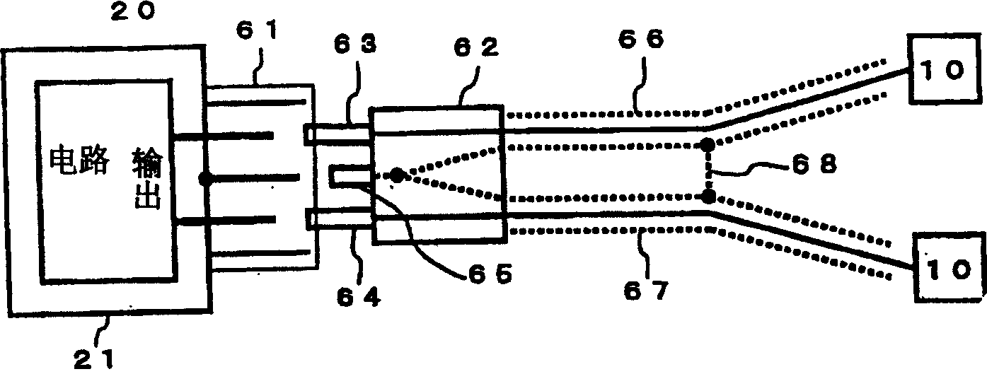
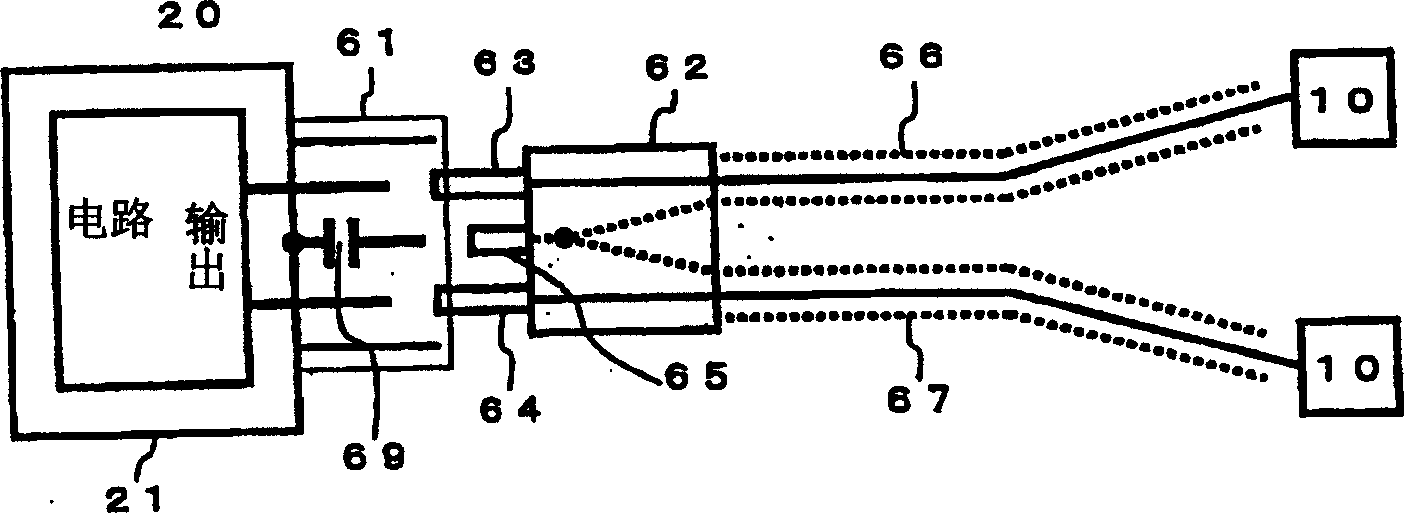
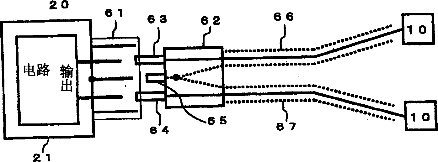
[0016] The matching circuit 55 is a circuit with balanced output. In order to make the output of the amplifier circuit 53 irradiate efficiently on the object to be heated, the output impedance of the amplifier circuit 53 is converted into the impedance between the output heads. The matching circuit 55 adjusts matching by rotating a variable capacitor within the matching circuit 55 with, for example, a motor 57 . The two balanced output terminals (connect...


PUM


Abstract

One household electric wave heater with relatively low radiated noise is provided. The electric wave heater with two electrode plates to hold the heated matter and to supply heating HF current is provided with a balanced output device, in which the central conductors of two coaxial cables are connected to two electrode plates separately to output terminals of the electric wave heater while the outer conductors of two coaxial cables are earthed to the side of the electric wave heater casing. In addition, the outer conductors of two coaxial cables are connected between the sides of the electric wave heater casing and the sides of the electrode plates. The said structure can reduce the HF current flowing through the outer conductors of the coaxial cables and the radiation noise to affect the peripheral electronic machines.

Description

technical field [0001] The present invention relates to a household electric wave heater which can be used for heat therapy of arms or feet; in particular, it relates to a kind of electromagnetic wave irradiating with short wave or ultrashort wave (HF~VHF) frequency band to make the body and other heated objects soaked by electromagnetic wave Tissue self-heating household electric wave heater. Background technique [0002] In the past, a heating device that uses high-frequency induction heating on the same principle as an induction cooker to increase body temperature has been known. Although this device can use electromagnetic waves with a high output power of 200~500W to the affected area to kill cancer cells, but because of High power necessitates cooling of other parts of the body surface. In addition, the device heats water molecules by vibrating them, usually using electromagnetic waves in the 2500MHz UHF band. However, since the above frequency has a short wavelength...

Claims


Application Information

Patent Timeline
Patent Type & Authority Applications(China)
IPC IPC(8): A61B18/18A61F7/00A61N5/02
Inventor 都築俊宏田村实
Owner MARUTAKA CO LTD
Why Eureka
Try Eureka