High-freqency current supressor capable of being easily attached to cable or like and earphone system using same
A high-frequency current and suppressor technology, which is applied to the structural components of transient suppressors, transmission systems, earpiece/earphone accessories, etc., and can solve problems such as electronic information equipment failures
- Summary
- Abstract
- Description
- Claims
- Application Information
AI Technical Summary
Problems solved by technology
Method used
Image
Examples
no. 1 example
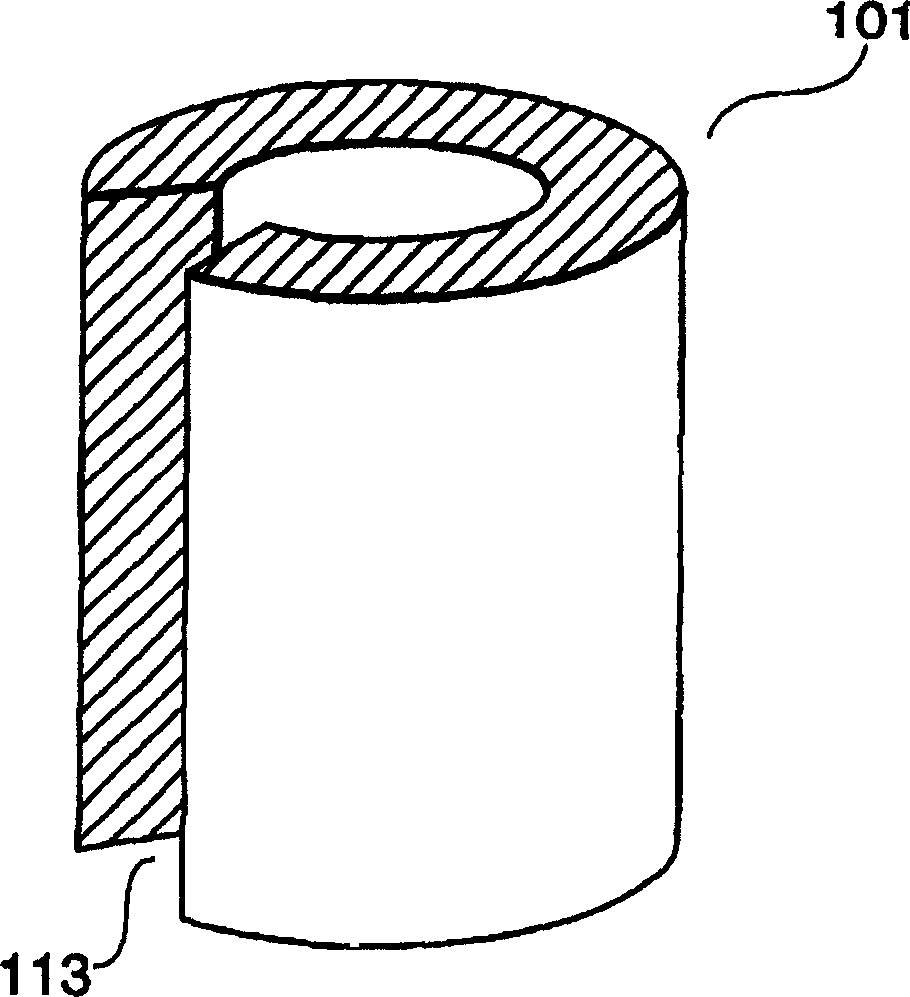
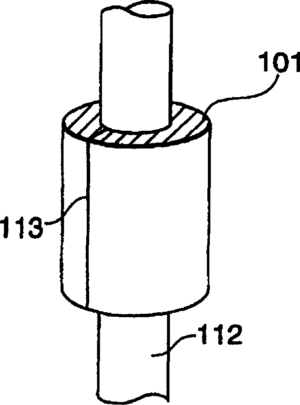
[0046] First, referring to FIG. 1(a) and FIG. 1(b), a high-frequency current suppressor according to a first embodiment of the present invention will be described.
[0047] As shown in FIG. 1( a ), the high-frequency current suppressor 101 is substantially composed of a composite magnetic material including soft magnetic powder obtained by flattening an alloy powder including at least Fe, Si, and Al, and a binder material. The composite magnetic material is molded into a cylinder with an inner diameter of 1.5 mm, an outer diameter of 2.65 mm, and a length of 10.0 mm. The composite magnetic material has a split 113 on a portion of the cylinder along its length. Therefore, the molded composite magnetic material has flexibility.
[0048] On the other hand, FIG. 1(b) shows a case where a high-frequency current suppressor 101 composed of a composite magnetic material is mounted to a signal cable 112 whose outer diameter dimension is about 1.5 mm. As described above, the high-freq...
no. 2 example
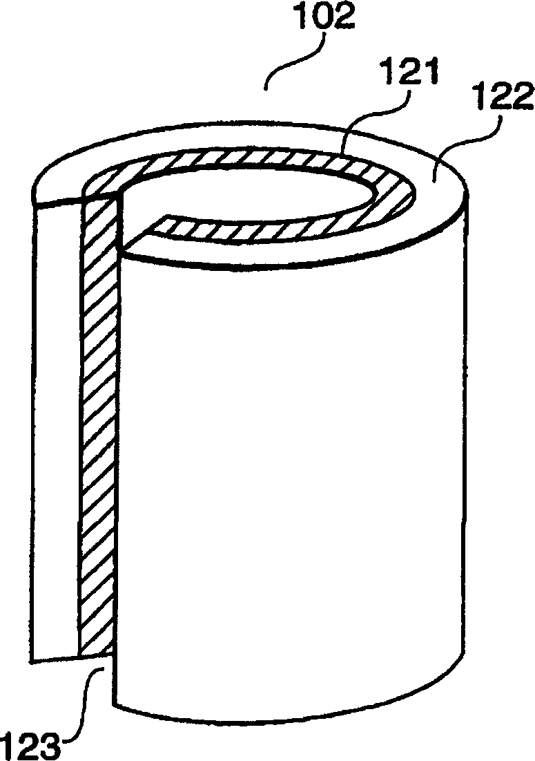
[0052] Next, refer to figure 2 A high-frequency current suppressor according to a second embodiment of the present invention will be described.
[0053] Such as figure 2 As shown, the high-frequency current suppressor 102 includes two layers consisting of a high-frequency current suppressing layer 121 and a resin outer layer 122 . The high-frequency current suppressing layer 121 is substantially composed of a composite magnetic material to have flexibility, which is the same as the first embodiment. The outer periphery of the high-frequency current suppressing layer 121 is covered with a resin outer layer 122 composed of molded resin with a thickness of about 0.5 mm to have flexibility.
[0054] Furthermore, as in the first embodiment, in the high-frequency current suppressor 102, both the high-frequency current suppressing layer 121 and the resin outer layer 122 have flexibility. Assume that the slit 123 of the high-frequency current suppressor 102 is separated by hand or ...
no. 3 example
[0057] Next, refer to image 3 A high-frequency current suppressor according to a third embodiment of the present invention will be described.
[0058] Such as image 3 As shown, the high-frequency current suppressor 103 includes two layers consisting of a high-frequency current suppressing layer 131 and an aluminum outer layer 132 . The high-frequency current suppressing layer 131 is substantially composed of a composite magnetic material to have flexibility, which is the same as the first embodiment. The outer periphery of the high-frequency current suppressing layer 131 is covered with an aluminum outer layer 132 composed of molded aluminum having a thickness of about 0.3 mm to have flexibility.
[0059] Furthermore, as in the second embodiment, in the high-frequency current suppressor 103, both the high-frequency current suppressing layer 1321 and the aluminum outer layer 132 have flexibility. Assume that the slit 133 of the high-frequency current suppressor 103 is sepa...
PUM
| Property | Measurement | Unit |
|---|---|---|
| length | aaaaa | aaaaa |
| thickness | aaaaa | aaaaa |
| thickness | aaaaa | aaaaa |
Abstract
Description
Claims
Application Information
 - R&D
- Intellectual Property
- Life Sciences
- Materials
- Tech Scout
- Unparalleled Data Quality
- Higher Quality Content
- 60% Fewer Hallucinations
Browse by: Latest US Patents, China's latest patents, Technical Efficacy Thesaurus, Application Domain, Technology Topic, Popular Technical Reports.
© 2025 PatSnap. All rights reserved.Legal|Privacy policy|Modern Slavery Act Transparency Statement|Sitemap|About US| Contact US: help@patsnap.com


