Valve mechanism for tubular fluid container

A technology of fluid container and valve mechanism, which is applied in the field of valve mechanism and can solve the problems such as no report on the valve mechanism

Inactive Publication Date: 2004-01-28
增田胜利
View PDF1 Cites 17 Cited by
  • Summary
  • Abstract
  • Description
  • Claims
  • Application Information

AI Technical Summary

Problems solved by technology

However, as of now, valve trains satisfying these requirements have not been reported

Method used


Image

  • Valve mechanism for tubular fluid container
  • Valve mechanism for tubular fluid container
  • Valve mechanism for tubular fluid container

Examples


Embodiment Construction

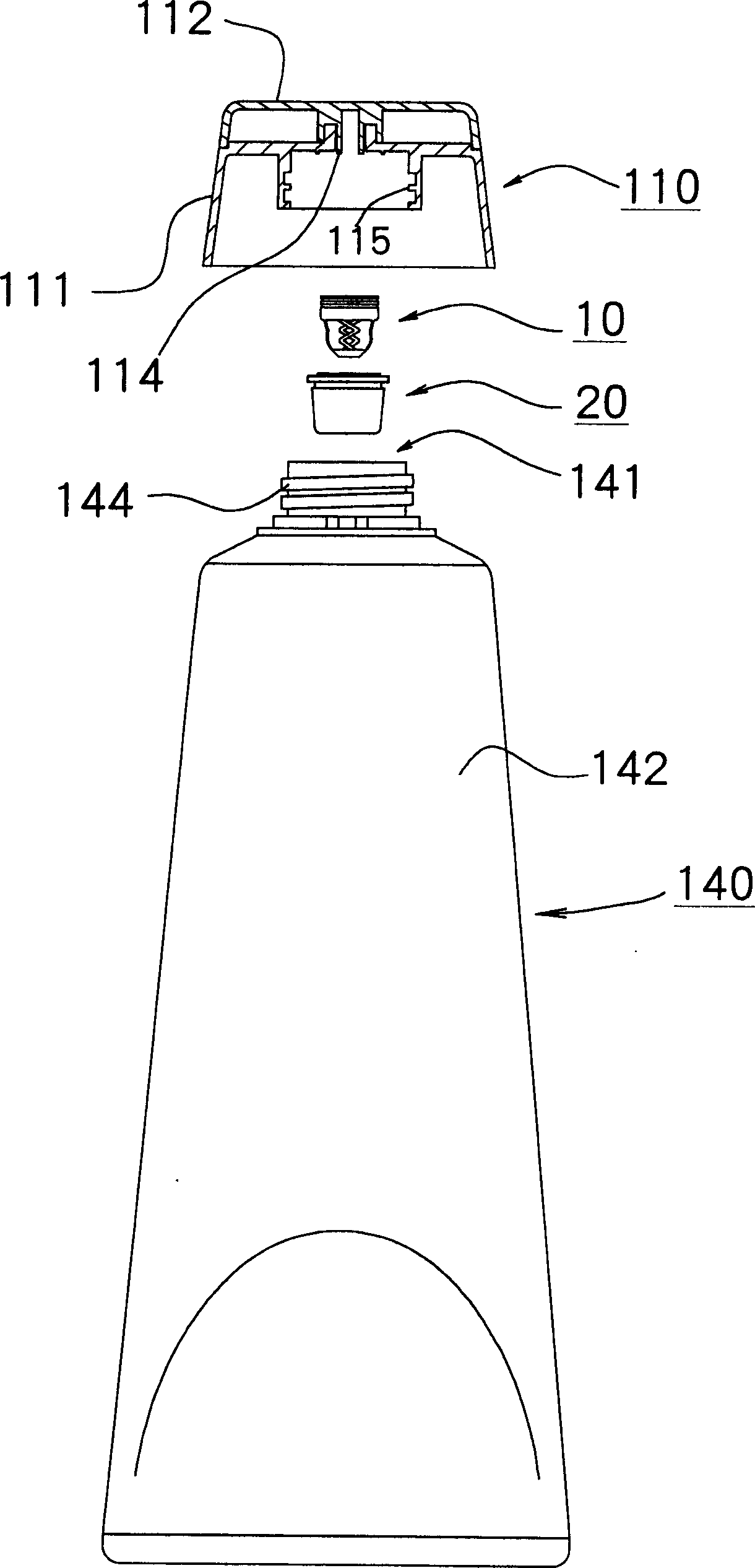
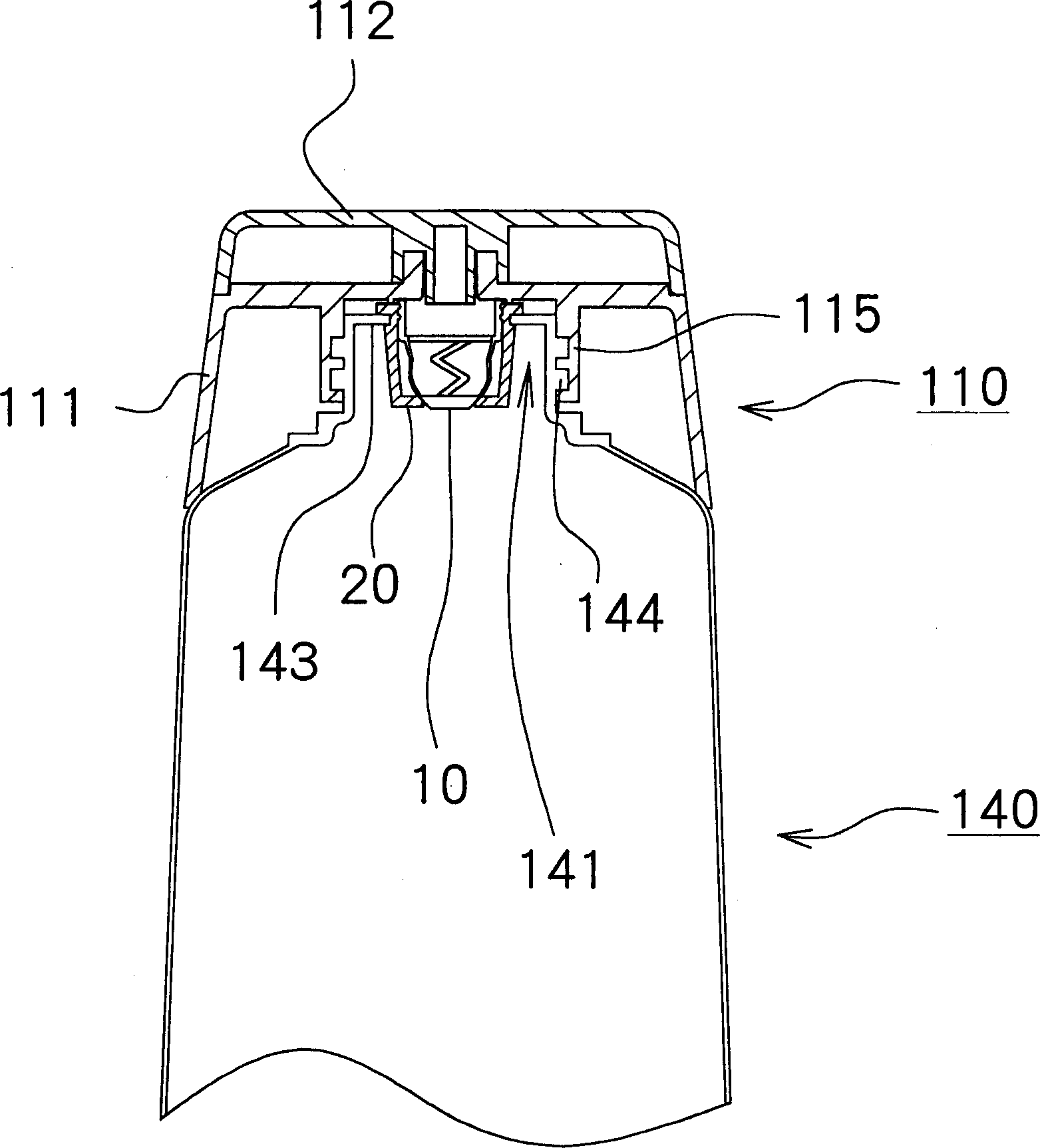
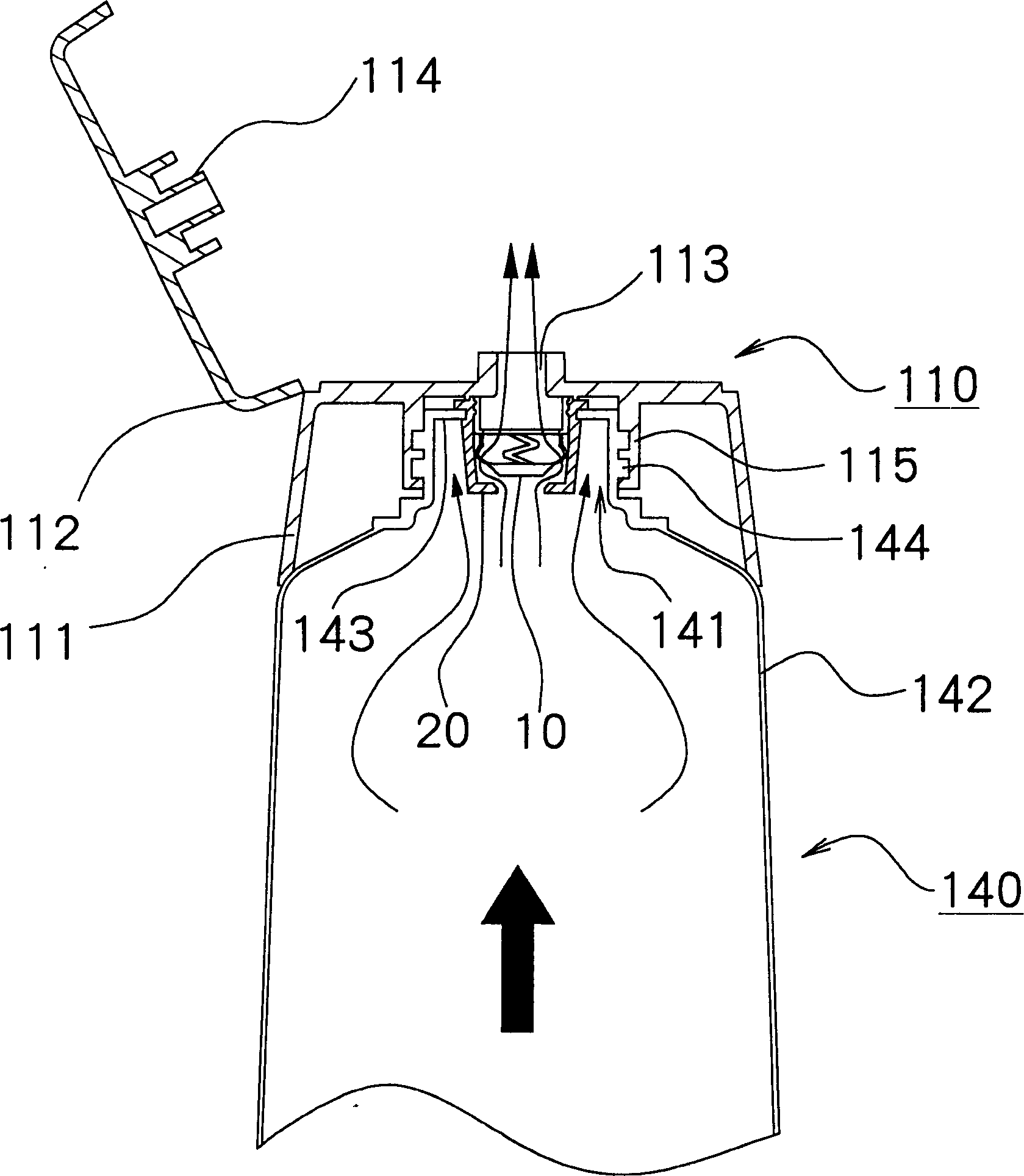
[0061] Preferred embodiments of the present invention will be described with reference to the accompanying drawings. The present invention is not limited to the Examples. figure 1 is an exploded view illustrating a tubular container to which a valve mechanism according to an embodiment of the present invention is applied; Figure 2 to Figure 4 is an enlarged view of relevant parts of a tubular container to which a valve mechanism according to an embodiment of the present invention is applied.

[0062]The tube-type container can be used for any suitable fluid container, including cosmetic products, which store gels (such as hair gels and cleansers) or creams (such as nourishing creams and cold creams used in the cosmetic field). Such tube-type containers can also be used as containers for medicines, solvents, foods, and the like.

[0063] In this illustration, highly viscous liquids, semi-fluids, gels of jelly-like substances solidified from sols, as well as creams and ordere...


PUM


Abstract

A valve seat portion 20 has a nearly tubular shape, at the bottom of which a circular opening portion 23 which functions as a valve seat is formed. A valve portion 10 has a ring-shaped supporting portion 11 which is disposed inside the valve seat portion 20. A valve body 12 has a shape corresponding to the circular opening portion 23, and multiple coupling portions couple the supporting portion 11 and the valve body 12. In the valve portion 10, the valve body can move between a closed position in which the valve body closes the opening portion 23 in the valve seat portion 20 and an open position in which the valve body opens the opening portion 23 by the flexibility of the four coupling portions 13.

Description

technical field [0001] The present invention relates to a valve mechanism, in particular to a valve mechanism that can be used for a tubular fluid container. Background technique [0002] As for this type of valve mechanism, for example, the valve mechanism described in Japanese Patent Laid-Open No. 2001-179139 has a spherical valve body and a spring that transmits power to the valve body toward the valve seat. However, valve mechanisms using spherical valve bodies and springs tend to be expensive to manufacture. [0003] Therefore, a generally used valve mechanism has a resin valve seat that moves between a closed position where the valve body contacts the valve seat and a resin valve body that moves between a closed position and an open position where the valve body contacts the valve seat. Seat separation. [0004] In the resin valve mechanism, it is preferable that the valve mechanism has a simple structure capable of sealing off the liquid flow reliably. Furthermore,...

Claims


Application Information

Patent Timeline
Patent Type & Authority Applications(China)
IPC IPC(8): B65D35/50B65D35/14B65D47/20B65D83/00
CPCB65D47/2075B65D83/0055B65D35/14B65D47/24
Inventor 增田胜利
Owner 增田胜利
Why Eureka
Try Eureka