Head position control method and disc device

A control method and detection head technology, applied in the direction of the transducing head device, the configuration/installation of the recording head, the recording/reproducing/deleting method, etc., which can solve the problem of longer time, no effective track number conversion method, recording/reproducing Reduced data processing capabilities and other issues, to achieve uniform seek speed, resolve differences, and improve performance

Inactive Publication Date: 2004-01-28
FUJITSU LTD
View PDF2 Cites 6 Cited by
  • Summary
  • Abstract
  • Description
  • Claims
  • Application Information

AI Technical Summary

Problems solved by technology

This causes a problem that the time until recording / reproducing data becomes long, that is, the processing capability of recording / reproducing data is reduced
[0034] Secondly, in the case of the prior art mentioned above, when a correction is made for the misalignment in the radial direction, an effective track number conversion method and a measurement method for determining the conversion value are not provided when a plurality of magnetic disks are used

Method used


Image

  • Head position control method and disc device
  • Head position control method and disc device
  • Head position control method and disc device

Examples


Embodiment Construction

[0094] Various embodiments of the present invention will now be described in the order of the disk storage device, the position demodulation structure, the offset correction method in the circumferential direction, the offset correction method in the radial direction, and other embodiments, but the present invention is not limited to Examples below.

[0095] [disk storage device]

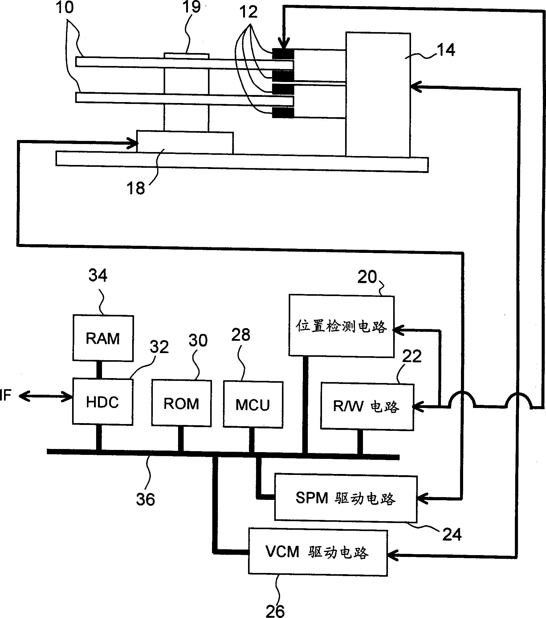
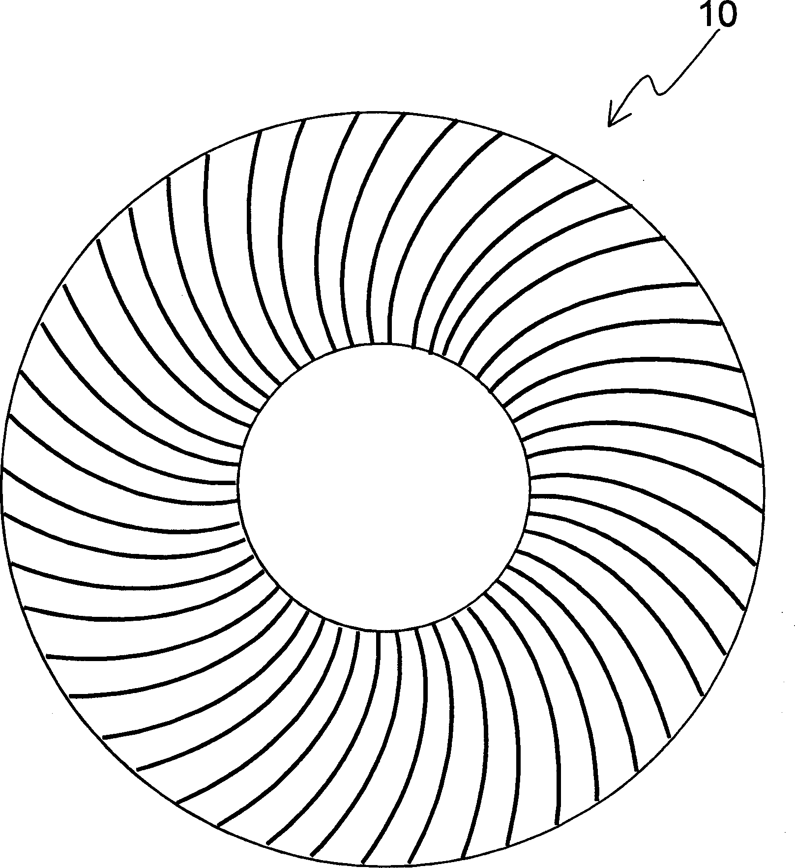
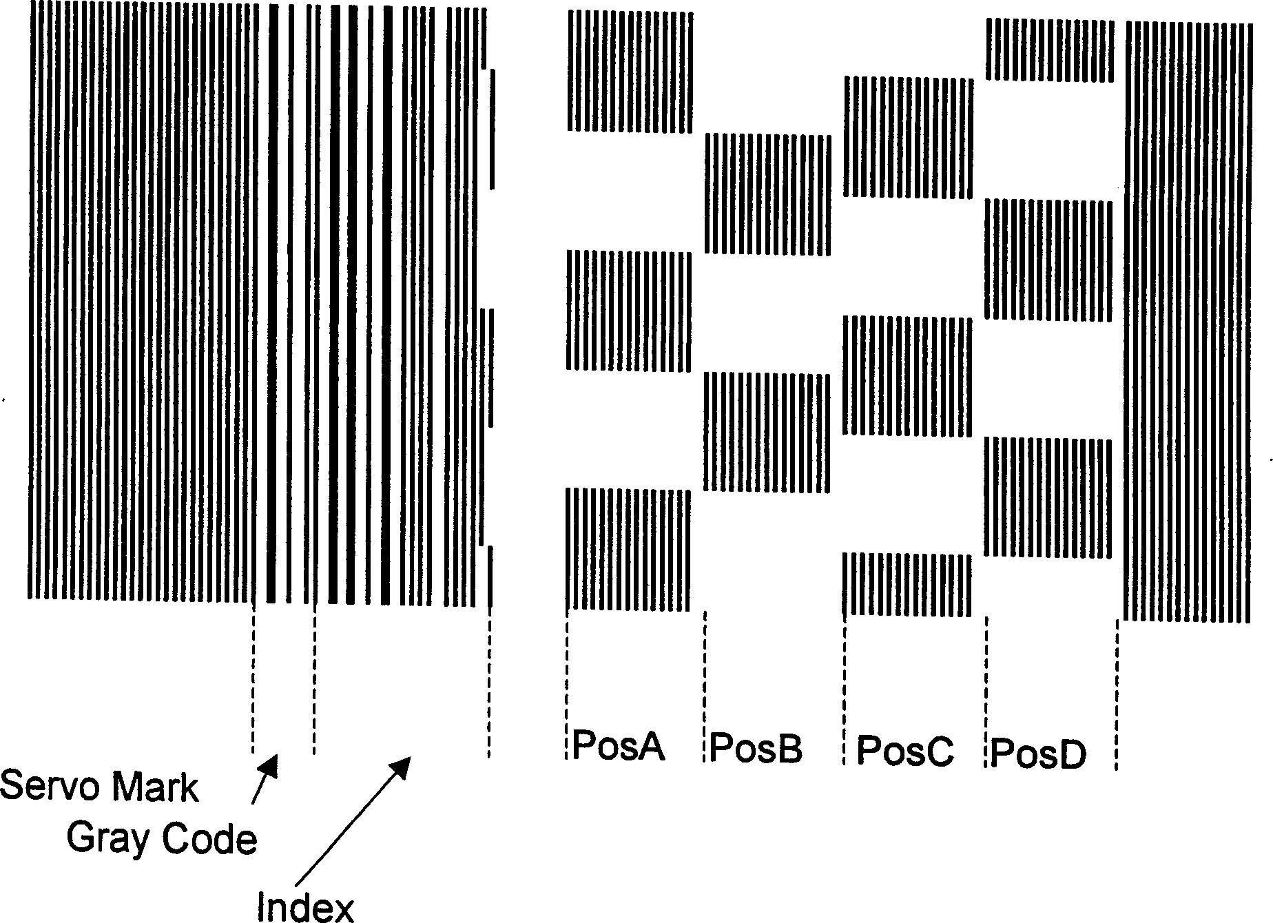
[0096] figure 1 is a schematic diagram of the structure of a disk storage device according to an embodiment of the present invention, figure 2 yes means figure 1 Schematic diagram of the position signal layout of the disk in, image 3 yes means figure 1 and figure 2 Schematic diagram of the structure of the position signal of the disk in Figure 4 yes means image 3 Schematic diagram of the detected waveform of the position signal in Figure 5 is a schematic diagram showing head position control.

[0097] figure 1 A magnetic disk device is shown as a disk storage device. like figu...


PUM


Abstract

A disk device that has displacement of servo signals in the circumference direction and radius direction between a plurality of disks, prevents a drop in performance due to the displacement when the heads are switched. To deal with the displacement in the circumference direction, the sector numbers on the disk are converted by a table for each head. Also the servo gate time is corrected by the table according to the eccentricity of the disk, so the servo signal detection accuracy improves. Also to deal with the displacement in the radius direction, the track numbers on the disk are converted by the table using the difference value based on the reference head.

Description

technical field [0001] The present invention relates to a head position control method and disk device for controlling the position of a read head or a read / write head on a rotating storage disk, and more particularly to head position control in a disk device having two or more heads The method and disk device thereof, wherein each head corresponds to one of a plurality of disk surfaces. Background technique [0002] A disk device using a storage disk is widely used as a storage device. Fig. 36 is a schematic diagram showing the structure of a conventional memory disk device. As shown in FIG. 36, the disk device is composed of a disk 94 for storing data, a spindle motor 96 for rotating the disk 94, a head 90 for recording and reproducing information on the disk 94, and a head 90 for moving the head 90 to the target. The position actuator 92 constitutes. Typical disk devices are magnetic disk devices (HDD: Hard Disk Drive) and optical disk devices (DVD and MO). [0003] I...

Claims


Application Information

Patent Timeline
Patent Type & Authority Applications(China)
IPC IPC(8): G11B20/10G11B5/55G11B5/596G11B20/20G11B21/08G11B21/10
CPCG11B5/59627G11B21/083G11B5/5534G11B5/5526G11B21/10
Inventor 高石和彦
Owner FUJITSU LTD
Why Eureka
Try Eureka