
Pixel unit of organic light-emitting diode

A technology of light-emitting diodes and pixel units, which is applied to instruments, identification devices, static indicators, etc., can solve the problems of darkening of organic light-emitting diode displays and low brightness of organic light-emitting diode pixel units.

Inactive Publication Date: 2004-02-11
AU OPTRONICS CORP
View PDF0 Cites 19 Cited by
  • Summary
  • Abstract
  • Description
  • Claims
  • Application Information

AI Technical Summary

Problems solved by technology

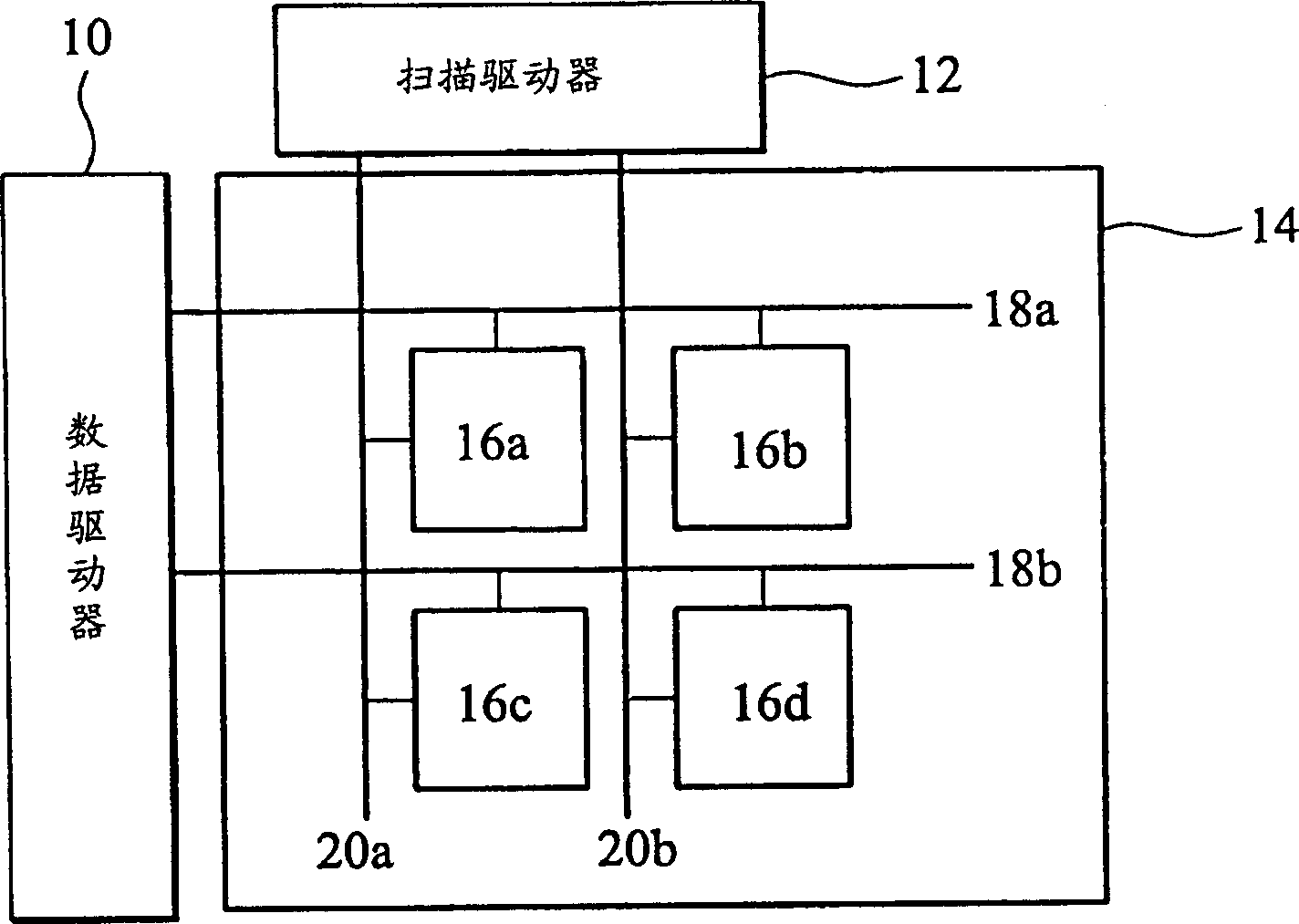
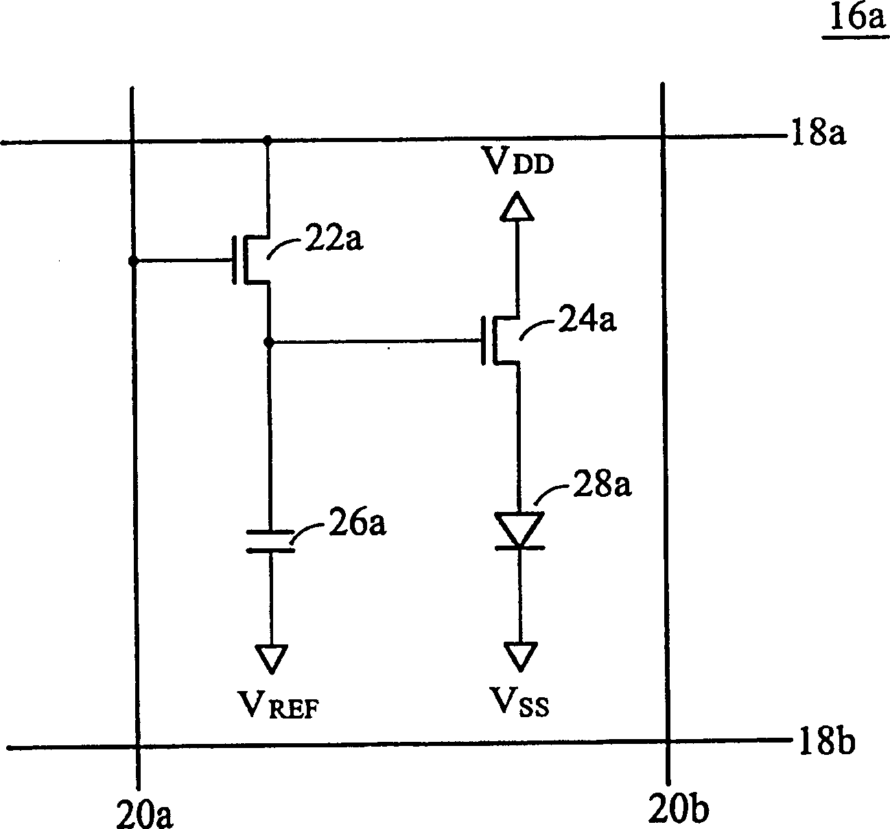
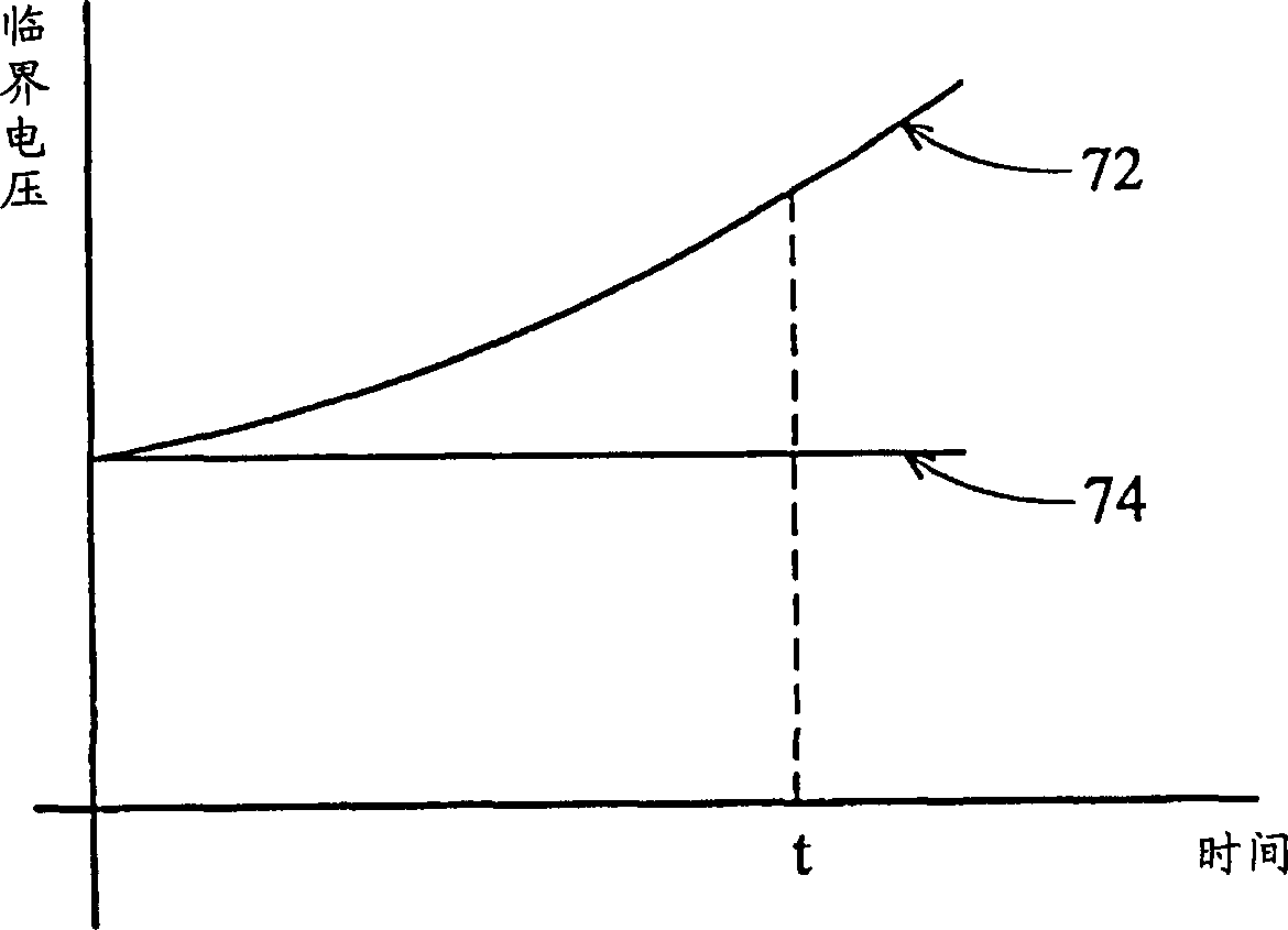
And so on, as time goes by, the brightness of each OLED pixel unit becomes lower, and the entire OLED display becomes darker.

Method used


Image

  • Pixel unit of organic light-emitting diode
  • Pixel unit of organic light-emitting diode
  • Pixel unit of organic light-emitting diode

Examples


Embodiment Construction

[0019] First preferred embodiment:

[0020] Figure 4 It is a circuit diagram of the OLED pixel unit in the first preferred embodiment. The OLED pixel unit 36a has a switching transistor 42a, a first driving transistor 44a, a capacitor 46a, an OLED 48a and a second driving transistor 50a. Wherein, the driving mode of the OLED pixel unit 36a is driven in an inversion mode, that is, if the pixel 36a needs to be always lit, the voltage of the data line will change periodically with time, as Figure 5 As shown, it is defined here: when the data line voltage is high (High), it is forward driving, and when the data line voltage is low (Low), it is reverse driving. When the scan signal activates the scan line 40a, the signal of the data line 38a is stored in the capacitor 46a through the switching transistor 42a, and the capacitor 46a stores the data signal in the form of a voltage. When driving forward, the capacitor 46a stores a positive voltage; when driving negatively, the cap...


PUM


Abstract

The present invention provides a kind of organic light-emitting diode display panel in the form of active array. Each of the organic light-emitting diode pixel unit has at least two driving transistors, and is suitable for using reverse mode for forward and reverse driving.

Description

technical field [0001] The present invention is an active matrix organic light emitting diode (OLED) display panel, and particularly relates to an inverting method to drive the OLED. Background technique [0002] Organic Light Emitting Diode (OLED, Organic Light Emitting Diode) display is a thin-film laminated display using organic compounds as light-emitting materials. Organic light emitting diode displays can be divided into active matrix and passive type according to their driving methods. The active matrix AM-OLED is driven by current, and each organic light emitting diode pixel unit must have at least one The switching thin film transistor (switch TFT) is used as the storage switch and addressing of the image data; in addition, a driving TFT is needed to adjust the driving current according to the difference in the storage voltage of the capacitor, that is, to control the organic light emitting diode pixel. Cell brightness and grayscale are different. [0003] General...

Claims


Application Information

Patent Timeline
IPC IPC(8): G09F9/33G09G3/3225
Inventor 宋志峰
Owner AU OPTRONICS CORP
Learn More