

Local network exchange method and local network exchanger
A switch and frame mapping technology, applied in data exchange network, data exchange through path configuration, network interconnection, etc., can solve the problem that users cannot fully enjoy the benefits of Ethernet, and achieve the effect of easy development and operation
- Summary
- Abstract
- Description
- Claims
- Application Information
AI Technical Summary
Problems solved by technology
Method used
Image

Examples
Embodiment (1
[0148] Embodiment (1): VLAN mapping as required
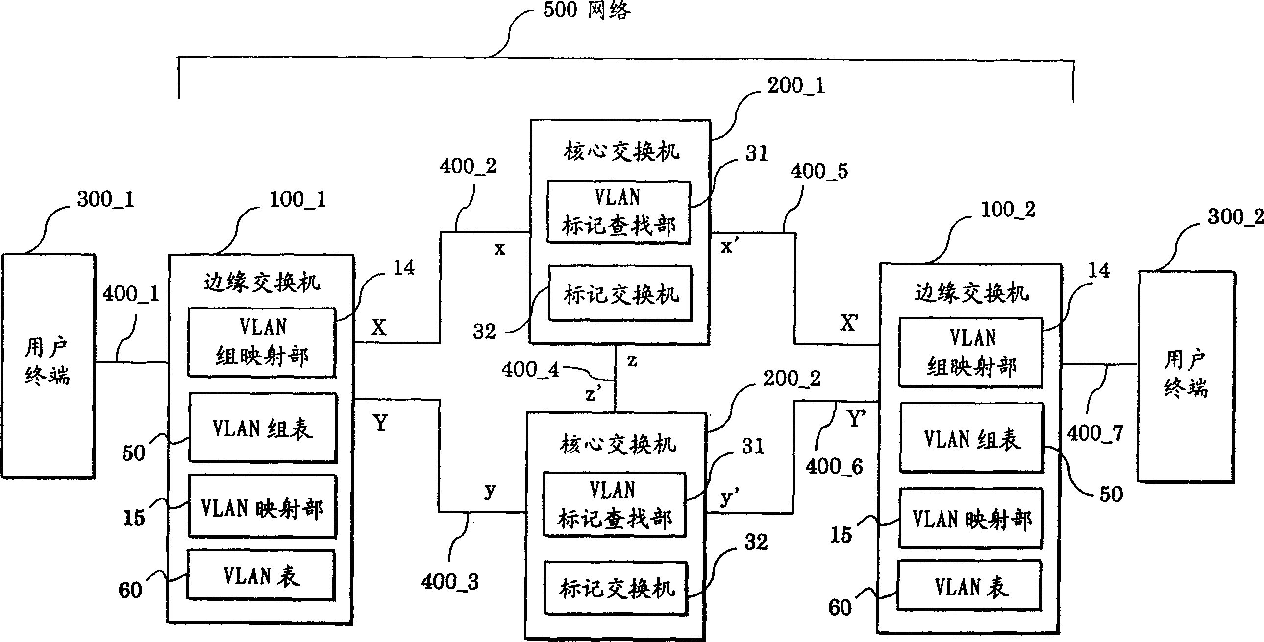
[0149] Figure 7 The embodiment (1) of the LAN switch 100 according to the present invention is shown. The LAN switch 100 is equivalent to, for example, the edge switch 100_1, and the edge switch 100_1 receives data from figure 1 The frame 800 of the user terminal 300_1 in the network 500.
[0150] The LAN switch 100 is provided with: an input interface 11, a flow controller 12, a frame analyzer 13, an ID / header distribution unit 16, a switching fabric (switching fabric) 17, and an output interface 18, which are cascaded together to sequentially receive The arrived frame 800 is processed.
[0151] The LAN switch 100 is also provided with a VLAN group mapping section 14, a VLAN group table 50a, a VLAN mapping section 15, and a VLAN table 60a.
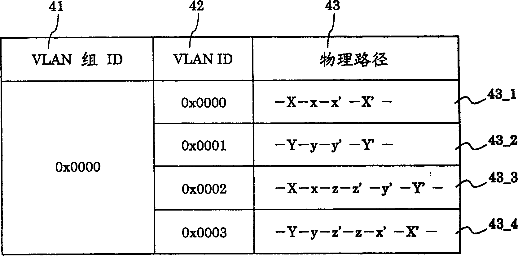
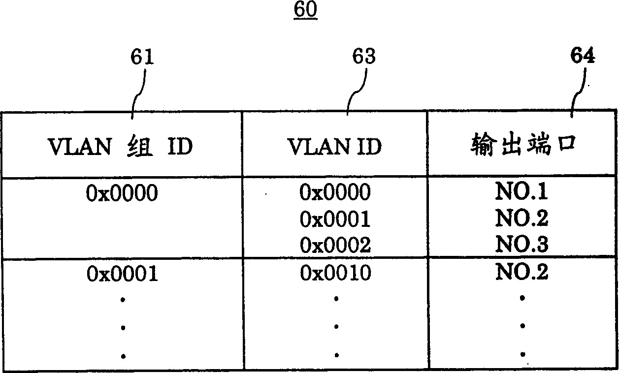
[0152] Figure 8 An example of the VLAN group table 50a for mapping VLAN groups using the port method is shown. In this table 50a, the input port 51, the VLAN group ID 52, and the validity...
Embodiment (2
[0179] Embodiment (2): VLAN mapping based on line failure
[0180] Picture 11 The embodiment (2) of the LAN switch 100 according to the present invention is shown. The LAN switch and Figure 7 The difference of the LAN switch 100 of the illustrated embodiment (1) is that a line failure detector 19 is further provided, and the VLAN table 60a is replaced with a VLAN table 60b.
[0181] The basic operation of the LAN switch 100 in the embodiment (2) is the same as that of the LAN switch 100 in the embodiment (1). Therefore, the following will mainly describe operations different from those of the embodiment (1).
[0182] It should be noted that the basic operations will also be briefly described in the following embodiments (3) to (10).
[0183] In the present embodiment (2), the line failure detector 19 detects the line failure, and the VLAN table 60b shows the VLAN using the line in which the failure has occurred, so that it may not be used.
[0184] Picture 12 One embodiment of...
Embodiment (3
[0204] Embodiment (3): Sequence switching of VLAN mapping
[0205] Figure 14 The embodiment (3) of the LAN switch 100 according to the present invention is shown. The LAN switch and Figure 7 The LAN switch 100 of the illustrated embodiment (1) is different in that the VLAN table 60a is replaced by the VLAN table 60c.
[0206] The LAN switch 100 of the embodiment (3) does not dynamically change / select VLANs as needed like the LAN switch of the embodiment (1), but sequentially selects VLANs.
[0207] Figure 15 One embodiment of the VLAN table 60c is shown. The VLAN table 60c and VLAN table 60a (see Picture 9 The difference of) is that the following items are added, that is, the subsequent activation 68 of the VLAN (VLANID 63) to be selected subsequently ("1": VLAN to be selected subsequently, "0": VLAN not to be selected). It should be noted that VLAN group table 50a and Figure 8 The VLAN group tables of the illustrated embodiment (1) are the same.
[0208] The operation proc...
PUM
 Abstract
Description
Claims
Application Information