Buckle lock structure

A technology of locking and locking mechanism, which is applied in the direction of building structure, building fastening device, wing fan fastening device, etc., can solve the problems of affecting the installation space of other devices, damaging the appearance, etc.

Inactive Publication Date: 2004-03-10
QUANTA COMPUTER INC
View PDF0 Cites 3 Cited by
  • Summary
  • Abstract
  • Description
  • Claims
  • Application Information

AI Technical Summary

Problems solved by technology

[0003] However, on the premise of not affecting the integrity of the appearance of the notebook computer, or when there are other devices that need to be installed ...

Method used


Image

  • Buckle lock structure
  • Buckle lock structure
  • Buckle lock structure

Examples


Embodiment Construction

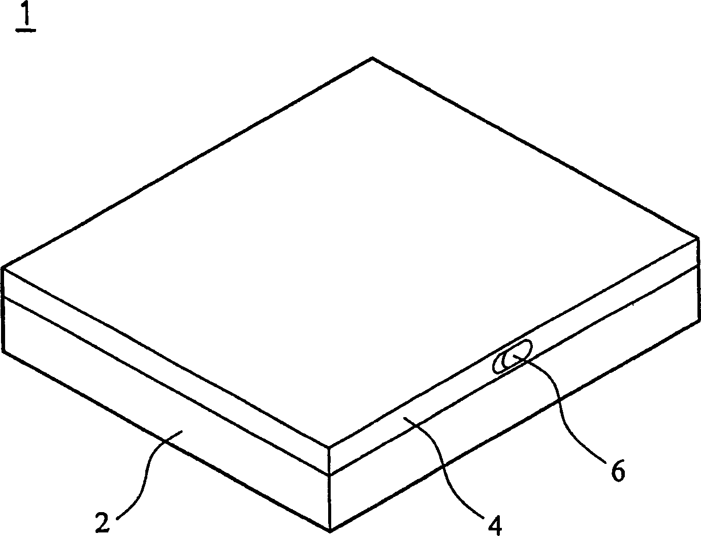
[0014] see Figure 2A and Figure 2B , the buckle lock structure 10 of the present invention is arranged on a notebook computer (such as figure 1 As shown), it is used to support the LCD screen and the host computer, and the notebook computer has two symmetrically arranged locking structures 10 .

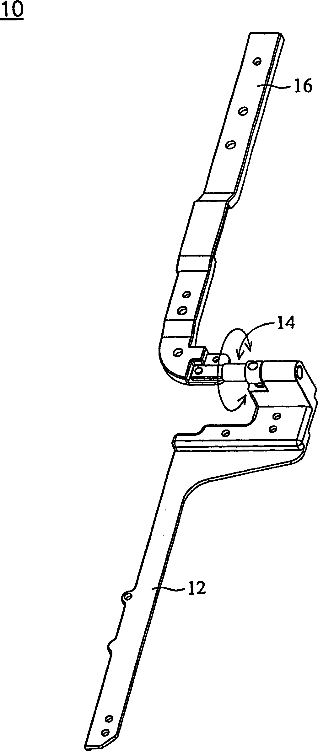
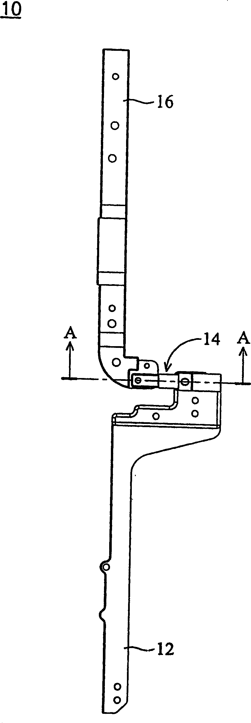
[0015] The locking structure 10 of the present invention mainly includes a first bracket 12 , a locking mechanism 14 and a second bracket 16 . The first bracket 12 and the second bracket 16 are respectively disposed in the host computer and the LCD screen of the notebook computer, so as to achieve the purpose of supporting the host computer and the LCD screen. Here, the locking mechanism 14 also serves as a hinge between the first bracket 12 and the second bracket 16 , so that the second bracket 16 can rotate relative to the first bracket 12 .

[0016] see image 3 , the locking mechanism 14 has a spring 141 , a latch 142 and a shaft 143 . The spring 141 is arranged in the firs...


PUM


Abstract

A padlock mechanism is composed of the first bearer, a locking unit and the second bearer. Said locking unit has a spring in the first bearer, a bolt on the spring and an axle rod pivoted to the first bearer and pushing said bolt. Said axle rod has also a recess. Said the second bearer linked with said axle rod can be turned to make the recess on axle rod come to the position above said bolt, and under the action of spring, the bolt comes in the recess.

Description

technical field [0001] The invention relates to a buckle lock structure, in particular to a buckle lock structure combined with a support mechanism. Background technique [0002] Generally speaking, a traditional notebook computer 1 is mainly composed of a host computer 2 and a liquid crystal screen 4, such as figure 1 shown. When the LCD screen 4 is covered on the host 2 , a lock 6 is used to fasten the LCD screen 4 to the host 2 . This kind of lock 6 can be arranged on the LCD screen 4 . Meanwhile, the notebook computer 1 can have one or more locks 6 to achieve the purpose of fastening the LCD screen 4 to the host 2 . [0003] However, on the premise of not affecting the integrity of the appearance of the notebook computer, or when there are other devices to be arranged on the outside of the notebook computer, such as an infrared module device, the existence of the lock will spoil the appearance and affect the installation space of other devices. Contents of the invent...

Claims


Application Information

Patent Timeline
IPC IPC(8): E05C19/00
Inventor 施智腾罗肇渊
Owner QUANTA COMPUTER INC
Why Eureka
Try Eureka