Tumble-plating device

A barrel plating and roller technology, applied in the direction of electrodes, cells, electrolysis process, etc., can solve the problems of high thermal expansion rate, low precision of insulating layer formation, difficulty of roller rotation, etc.

Inactive Publication Date: 2004-03-24
上市 一吉
View PDF1 Cites 5 Cited by
  • Summary
  • Abstract
  • Description
  • Claims
  • Application Information

AI Technical Summary

Problems solved by technology

[0014] However, if the above-mentioned barrel plating device is used, the insulating layer of the lead wire is formed with low precision in the bearing portion, and the thermal expansion rate is high.
Therefore, for example, when electroplating the above-mentioned conductive sheet on a workpiece in which the conductive sheet is partially mounted on a small ceramic substrate with a length of 0.2 to 1 mm, it is difficult to place the side of the drum in consideration of the low precision of the formation of the insulating layer and the coefficient of thermal expansion. The inner diameter of the insertion hole 32b of the bushing 32a on the plate is controlled so that the above-mentioned workpiece or a part thereof does not enter the gap between the inner peripheral surface of the insertion hole 32b and the lead wire 10a, that is, the size of the gap of the bearing part.
[0015] Moreover, if the size of the insertion hole 32b of the bushing 32a cannot be properly controlled and the insertion hole 32b is relatively small, the inner peripheral surface of the insertion hole 32b and the outer peripheral surface of the lead wire 10a are strongly opposed to each other when the drum rotates. Friction, making the rotation of the drum difficult
In addition, due to the wear of the insulating layer of the lead wire 10a, the gap between the two increases, causing the disadvantage that the workpiece or a part of the workpiece enters the gap.
In addition, if the size of the insertion hole 32b cannot be appropriately controlled or if the insertion hole 32b is relatively large, the workpiece or a part of the workpiece enters the gap when the drum rotates.
[0016] If the workpiece or a part of the workpiece enters the gap between the inner peripheral surface of the insertion hole 32b and the lead wire 10a, the gap will be blocked, and the insulating layer covering the lead wire 10a will be damaged, or the rotation of the drum will not be smooth, or the drum will be removed after plating. When the workpiece is taken out, the workpiece that blocks the above-mentioned gap remains in the drum, which reduces the disadvantages of electroplating homogeneity

Method used


Image

  • Tumble-plating device
  • Tumble-plating device
  • Tumble-plating device

Examples


no. 1 Embodiment approach

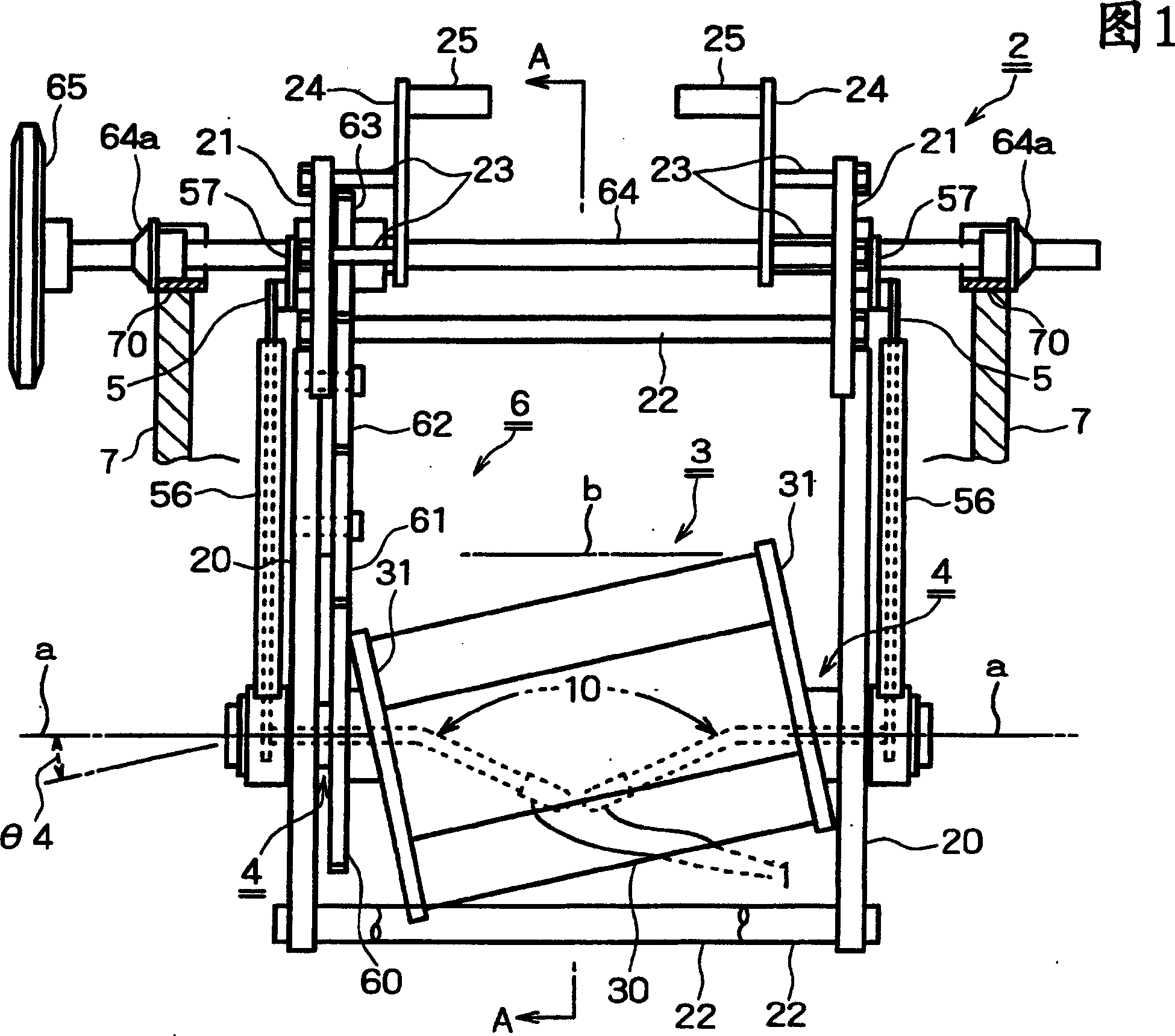
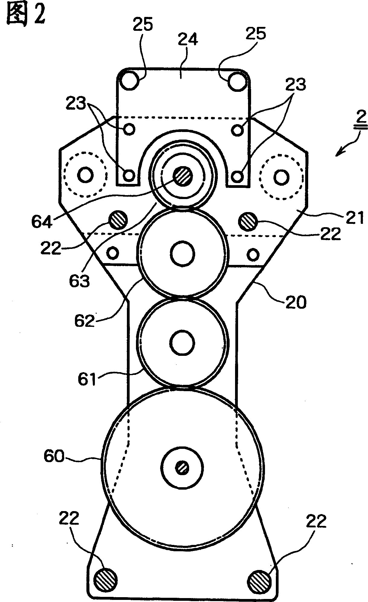
[0031] Hereinafter, first, the outline of the barrel plating apparatus of the present invention will be described with reference to FIGS. 1 and 2 .

[0032] Shown in Fig. 1 and Fig. 2, barrel plating device of the present invention has cylinder support frame 2, and this cylinder support frame 2 is contained in the electroplating bath 7, connects by the support member 20 of predetermined interval opposite by a plurality of connecting rods 22, 20. An upper support plate 21 is attached to the upper portion of each support member 20 .

[0033] The hollow support shafts 4 are respectively attached to penetrate from the outside at the same height of the lower part of each support member 20 . Except that both ends of the drum 3 are rotatably mounted on the support shaft 4, the lead wires 10 of the electrode (cathode) 1 are inserted through the interior in a non-rotatable and waterproof state.

[0034] The drum 3 is composed of a hollow cylinder 30 and end plates 31 , 31 . The holl...

no. 2 Embodiment approach

[0090] Fig. 10 is a partial sectional view showing a second embodiment of the electrode lead mounting structure of the present invention.

[0091] In this embodiment, the lead wire 10 and the current-carrying member 5 in the first embodiment are integrally formed, and the support shaft 4 is integrally formed without providing the cover portion 42 .

[0092] The other configurations and effects are substantially the same as those of the first embodiment, and description thereof will be omitted.

Embodiment approach

[0094] In each of the above-mentioned embodiments, the bushing 32 is installed in the insertion hole 312 on the end plate 31 of the drum 3, but the bushing 32 may be omitted. When the drum 3 rotates, the inner peripheral surface of the insertion hole 312 is relatively The outer peripheral surface of the sleeve 12 slides.

[0095] In the first embodiment, the adjustment plate 46 for adjusting the posture of the lead wire 10 is fixed to the current-carrying member 5 with the screw 47, but the adjustment plate 46 is fixed to the support shaft 4 (connecting part cover 41) with the same screw 47, and has the same Effect.

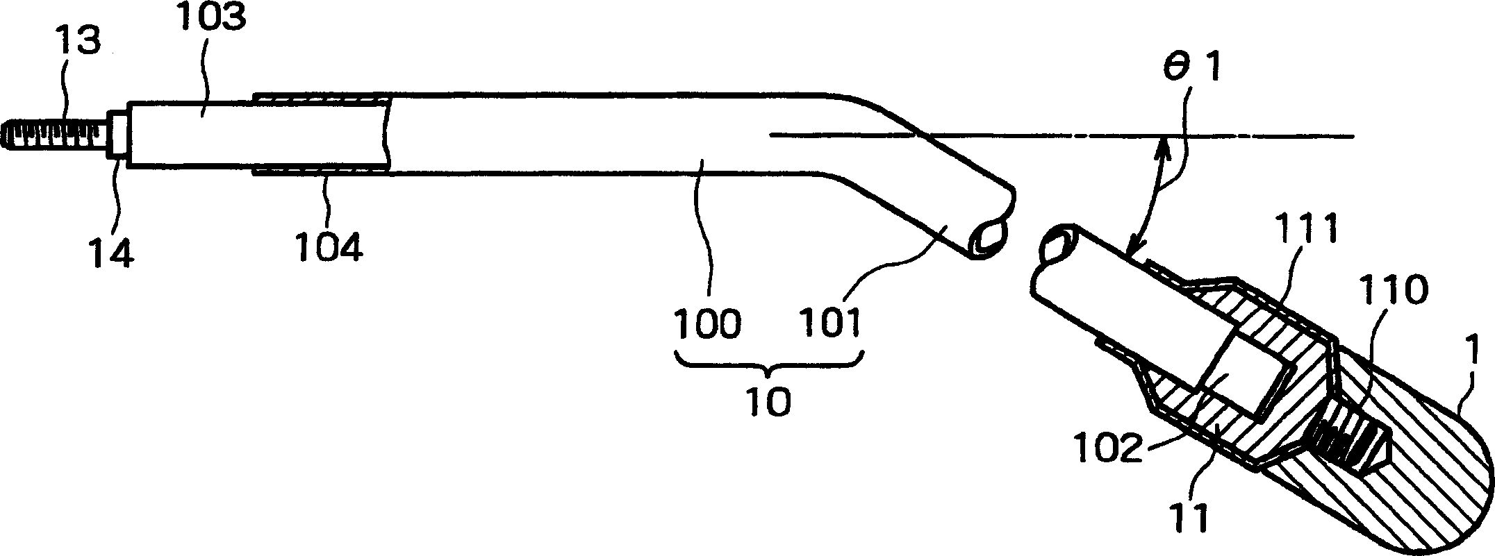
[0096] In the above embodiment, the bent portion 101 of the lead wire 10 is formed in an oblique linear shape, but the bent portion 101 may be formed in an arc shape or a polygonal shape, and may be formed in a convex shape obliquely upward or downward.

[0097] As adopt barrel plating device of the present invention, lead wire 10 runs through the bearing part o...


PUM


Abstract

To provide an electrode which can more uniformly and efficiently apply plating to an object for fine plating and barrel plating equipment. The electrode consists of a hard conductive bar integrally having a bending and lowering part exhibiting a downward shape continuously with a horizontal shaft part, has a juncture on the base end side of the shaft part and an electrode body on the tip side of the bending and lowering part, respectively, and is characterized in that the portions except the juncture and the electrode body are coated by insulating layers. The electrode is so mounted in a barrel inclined to a direction perpendicular to the center of the horizontal rotating shaft that the electrode body exists to face the revolving shaft at a level lower than the center of the shaft and that the shaft part exists in a non-rotatable state at both ends of the center of the revolving shaft. (C)2004,JPO.

Description

technical field [0001] The present invention relates to a barrel plating device, in particular to a barrel plating device suitable for implementing electroplating on small workpieces, for example, for the above-mentioned conductive plate on the object (workpiece) of a small ceramic substrate with a length of 0.2 to 1 mm. A barrel plating device for electroplating. Background technique [0002] As mentioned above, in the barrel plating device for electroplating small workpieces, it is important to prevent the small workpieces in operation from entering the electrode (cathode) lead wires installed at the rotating center at both ends of the drum and the through holes through which the lead wires are inserted. Clearance between (bearing part). The reason is that in the bearing part of the electrode lead wire, for the rotating drum, since the electrode lead wire is inserted non-rotatingly, if a small workpiece enters the bearing part, the insulating layer covering the lead wire ...

Claims


Application Information

Patent Timeline
IPC IPC(8): C25D17/12C25D17/18C25D17/20C25D21/00
Inventor 上市一吉
Owner 上市 一吉
Why Eureka
Try Eureka