Connector with movable contact aligning member

A technology of moving contacts and connectors, applied in the direction of two-part connection device, connection, connection part protective grounding/shielding device, etc.

Inactive Publication Date: 2004-04-14
TYCO ELECTRONICS JAPAN GK
View PDF1 Cites 2 Cited by
  • Summary
  • Abstract
  • Description
  • Claims
  • Application Information

AI Technical Summary

Problems solved by technology

Therefore, there arises a problem that external noise (or interference), suc...

Method used


Image

  • Connector with movable contact aligning member
  • Connector with movable contact aligning member
  • Connector with movable contact aligning member

Examples


Embodiment Construction

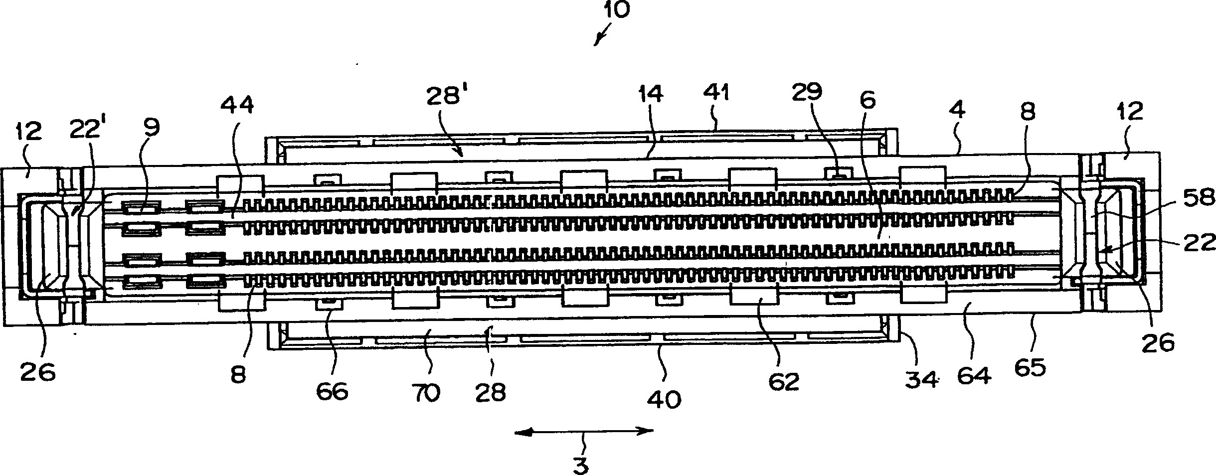
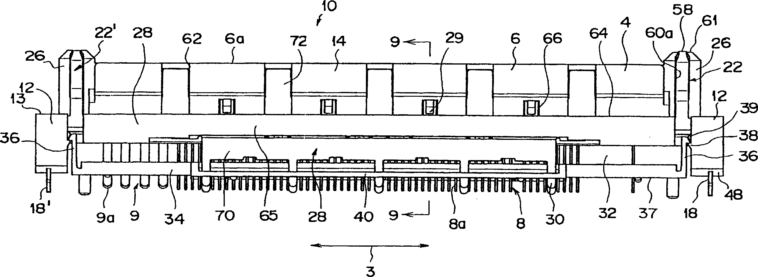
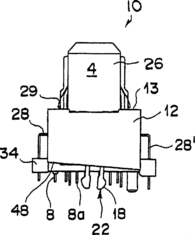
[0043] Hereinafter, a preferred embodiment of a plug connector (electrical connector having a movable contact aligning member) of the present invention will be described in detail with reference to the accompanying drawings. Figure 1 to Figure 4 A plug connector 10 is depicted. Each figure is, figure 1 is a floor plan, figure 2 is the front view, image 3 is the right side view, and Figure 4 A bottom view of the plug connector 10 is shown.

[0044] In the following, reference will be made to Figure 1 to Figure 4 Give a description. The plug connector 10 includes an elongated insulating housing 4 ; in the engaging portion 6 of the housing 4 , the contacts 8 and 9 are arranged in 4 rows, which are arranged in a longitudinal direction 3 of the housing 4 . Contact 8 is a narrow contact for signal transmission. Contact 9 is a wide contact for power transmission. The housing 4 includes a parallelepiped body 14 extending in the longitudinal direction 3 and parallelepiped ...


PUM


Abstract

An electrical connector has an insulative housing that is mounted on a circuit board. The insulative housing has a plurality of contacts with tines that extend through a bottom surface of the insulative housing for connection to the circuit board. A movable contact alignment member is positioned adjacent to the bottom surface of the housing and aligns the tines with the circuit board. The moveable contact alignment member is temporarily fixed to the insulative housing by latch arms and is urged into permanent fixture with the insulative housing by the circuit board when the insulative housing is mounted thereon. A shield member is attached to the insulative housing. The shield member has an extension portion configured to shield at least a portion of the tines that are exposed between the insulative housing and the movable contact alignment member.

Description

technical field [0001] The present invention relates to an electrical connector, in particular to a connector with a movable contact aligning member, which includes a shielding member for shielding electromagnetic waves, and a movable contact aligning member for aligning the contact tip. Background technique [0002] Generally, an electrical connector mounted on a printed circuit board (hereinafter, referred to simply as a "circuit board") is usually used as a device for electrically connecting a circuit board on a personal computer or other equipment, and the circuit board has electronic components mounted thereon. Electrical connectors are also used in portable personal computers for connecting parts for connecting various components on the back. When these electrical connectors used in electrical and electronic equipment are multi-pole connectors with a large number of contacts, movable contact alignment members are used. That is, the contact pin portions (tips) of the ...

Claims


Application Information

Patent Timeline
IPC IPC(8): H01R13/648H01R12/70H01R13/658
CPCH01R12/707H01R23/6873H01R12/7029H01R13/658
Inventor 笹目直孝桥本信一
Owner TYCO ELECTRONICS JAPAN GK
Why Eureka
Try Eureka