New disffuser in central air conditioning system

A technology of central air-conditioning system and diffuser, which is applied in the directions of space heating and ventilation details, household heating, piping arrangement, etc., can solve the problems of increasing production cost, time-consuming, and increasing cost, and achieves reduction of production cost and time-consuming assembly. reduced effect

Inactive Publication Date: 2004-05-05
拉梅什纳纳穆哈特
View PDF0 Cites 4 Cited by
  • Summary
  • Abstract
  • Description
  • Claims
  • Application Information

AI Technical Summary

Problems solved by technology

[0012] 2. Since the disperser is made of several plates and assembled together, the manufacturing process is cumbersome, time-consuming and labor-intensive, which increases the production cost
[0013] 3. Sometimes there is a gap between the two side plates at the corner of the core during assembly, and the product is returned as a result, resulting in a large production loss, that is, material and labor loss, which increases production costs
[0014] 4. In order to avoid gaps at the corners of the core, the side plates of the core must be produced with high precision, which also increases the cost
[0015] 5. Since there are grooves for assembling the core on the rear side and the gusset, the weight of the diffuser is increased, which also increases the production cost
These welding and hemming operations require additional equipment and are also time consuming, increasing production costs
[0017] 7. Due to the grooves on the back surface of the core, the corner plates or ridges, and the solder joints, dust will accumulate here and it is difficult to clean
[0018] 8. Dust will also accumulate in the gaps at the corners of the front surface of the core, making the appearance of the diffuser dirty and detrimental to the interior decoration / appearance of the room / space

Method used


Image

  • New disffuser in central air conditioning system
  • New disffuser in central air conditioning system
  • New disffuser in central air conditioning system

Examples


Embodiment Construction

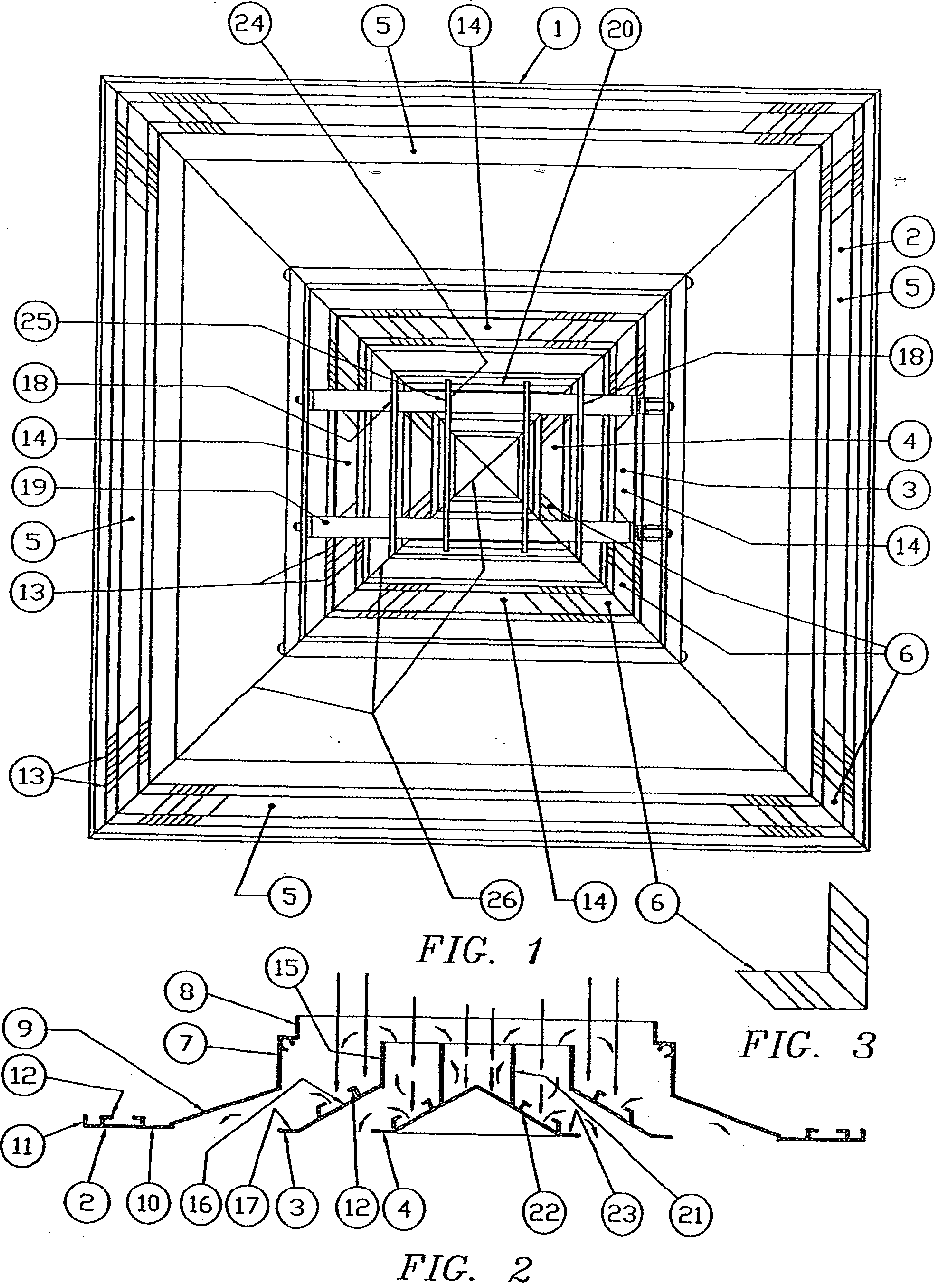
[0045] Referring to FIGS. 1 to 3 , a conventional disperser 1 includes an outer frame 2 , one or more intermediate cores 3 and a central core 4 . The outer frame 2 is made by assembling four side panels 5 with four corner panels 6 comprising vertical sides 7 bent at an angle 8 at the top, an outer bevel 9 at the bottom, and a substantially horizontal The flange 10, the outer free edge of the flange 10 is bent upwards as shown in Figure 11 to increase the strength. A groove 12 is formed on the upper / rear surface of the flange 10 to accommodate the gusset 6 when assembled. As shown at 13, four such side panels 5 are assembled together by means of gusset panels 6 and hemmed to secure the various pieces together. When assembling, the upper vertical sides of the upper square or rectangle of the outer frame depend on the size of the air duct to be assembled with the diffuser.

[0046]The central core 3 is also made of four side panels 14 assembled together by means of four corner ...


PUM


Abstract

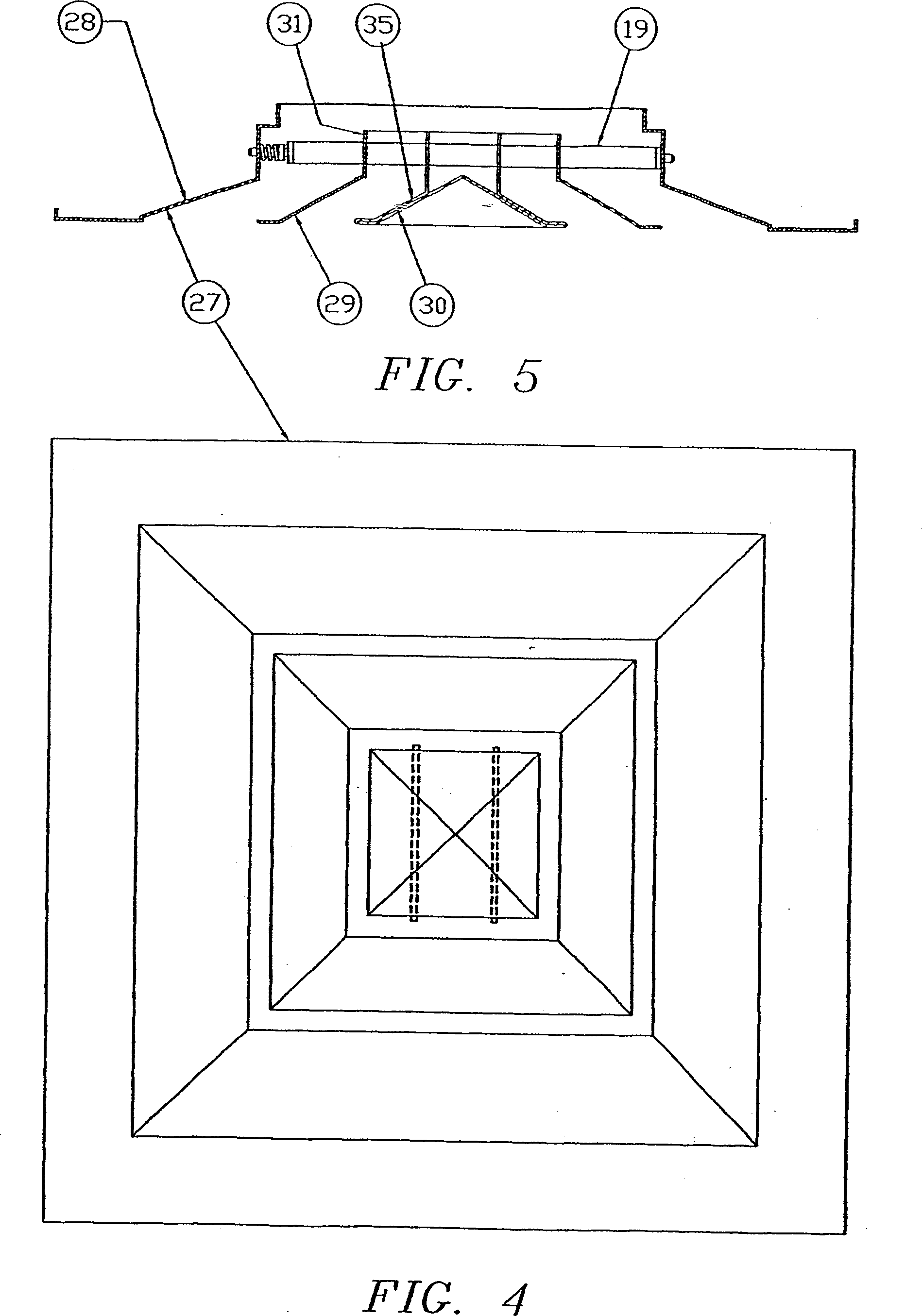
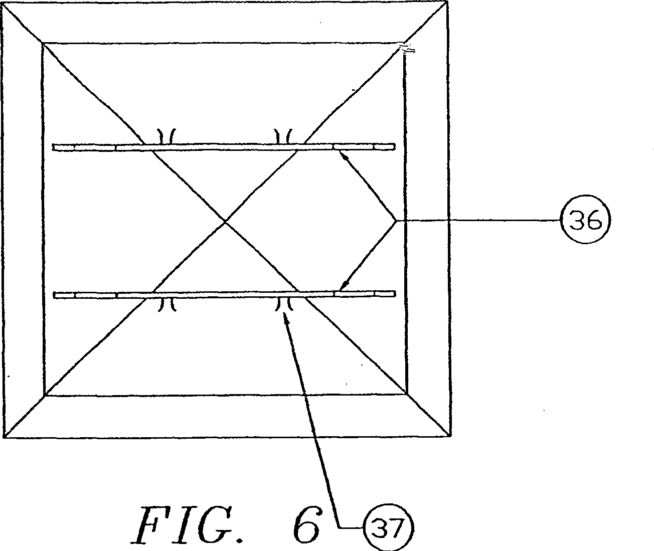
An improved diffuser (27) for central air conditioning system comprising of a single piece centre core (30), at least one intermediate core (29) and an outer frame (28), the single piece centre core consisting of an outwardly and downwardly directed slanting surface (35) originating from a centre point and ending into a substantially horizontal flange at its bottom periphery, a pair of vertical strips (36) attached at the back side of the slanting surface in spaced apart relationship and opposing to each other, at least a pair of spaced apart holes (25) provided in each vertical strips, the said intermediate core consisting of vertical collar (31) at its top, an outwardly and downwardly directed slanting surface (16) ending into a substantially horizontal flange (17) at its bottom, at least a pair of holes (25) provided into two opposing vertical sides (34) of the said collar, the said outer frame consisting of a vertical collar (7) at the top, an outwardly downwardly directed slanting surface (9) ending into a substantially horizontal flange (10), at least a pair of holes provided in two opposing sides of the said collar and at least one pair of rods (19) passing through the said holes for attaching the said centre core to the said intermediate core and said outer frame.

Description

technical field [0001] The present invention relates to a new type of diffuser for central air-conditioning system and its component parts, that is, decorative pattern or central core, core group, outer frame, etc., and its manufacturing method. Background technique [0002] In the central air conditioning system, the air is adjusted to the desired temperature at the source and distributed to various locations through the air duct network, and a diffuser is required at each outlet of the air duct. [0003] Usually these ducts are of square or rectangular cross-section, most likely because they are readily self-supporting and fully adjustable in the roof corners of buildings or vehicles, and the diffusers used at the outlet of the distribution ducts are also square or rectangular in shape . [0004] A diffuser mounted at the end of an air distribution duct protrudes / exposes from the ceiling of a room or other area where air conditioning is required, so the diffuser can be pa...

Claims


Application Information

Patent Timeline
Patent Type & Authority Applications(China)
IPC IPC(8): F24F13/068F24F13/062
CPCF24F13/062F24F13/06
Inventor 拉梅什·纳纳·穆哈特
Owner 拉梅什纳纳穆哈特
Why Eureka
Try Eureka