Advanced pressure type flow control device

A flow control device and flow control technology, applied in the direction of flow control, flow control of electrical devices, measuring devices, etc., can solve the problems of slow response speed, high cost, and many troubles of mass flow regulators

Inactive Publication Date: 2004-05-05
FUJIKIN INC +2
View PDF1 Cites 22 Cited by
  • Summary
  • Abstract
  • Description
  • Claims
  • Application Information

AI Technical Summary

Problems solved by technology

However, the mass flow regulator has many disadvantages such as ①slow response speed, ②poor flow accuracy in the low flow area, ③more troublesome operation, and ④high cost.

Method used


Image

  • Advanced pressure type flow control device
  • Advanced pressure type flow control device
  • Advanced pressure type flow control device

Examples


Embodiment Construction

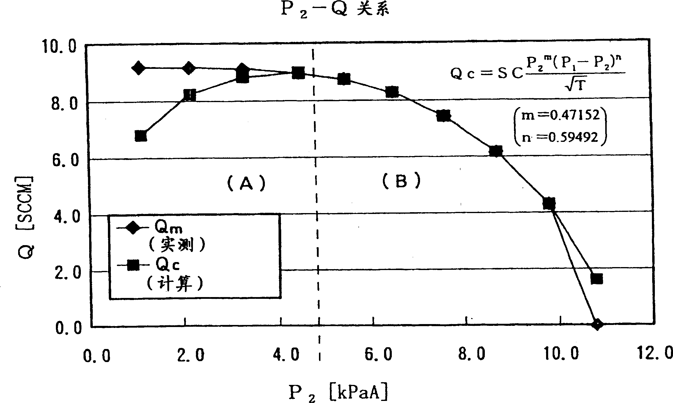
[0029] figure 1 It is a comparison diagram of the flow experimental formula and the flow measurement side under the non-critical condition of the present invention. The present inventors reviewed conventional theoretical flow formulas for non-critical conditions. The conventional flow formula derived by Bernoulli's theorem is Qc=K(P 2 (P 1 -P 2 )) 1 / 2 . Rewrite it as Qc=KP 2 1 / 2 (P 1 -P 2 )) 1 / 2 .

[0030] This known flow formula is correct for incompressible fluids. For example, it is a flow type with sufficient accuracy for fluids such as incompressible liquids. In order to make this flow formula suitable for compressive fluids such as gas, it is necessary to establish an experimental flow formula that does not change the structure as much as possible and has complex parameters.

[0031] Therefore, the present inventors propose to use Qc=KP 2 m (P 1 -P 2 ) n As an experimental flow formula, import m and n parameters for matching. Here, the constant of pro...


PUM


Abstract

Provided is an improved pressure-type flow rate control apparatus. The empirical formula for the compressible fluid under non-critical conditions (sub-sonic) is expressed as Qc=KP2(P1-P2) and the flow rate of fluid passing through orifice (4) is calculated by: Qc=KP2(P1-P2) (K is a proportional constant; and m and n are constants) so that the flow rate of fluid passing through the orifice can be controlled to the target flow rate with high precision at a high speed. Also provided is an improved pressure-type flow rate control apparatus in which a pressure ratio P2 / P1=r, obtained from an upstream pressure (P1) and a downstream pressure (P2) is constantly compared with a critical value (rc), and under critical conditions (r<=rc), the flow rate is calculated by: Qc=KP1. Under non-critical conditions (r>rc), the flow rate is calculated by Qc=KP2(P1-P2), so that the flow rate is controlled to the target flow rate with accuracy at a high speed depending upon the conditions of fluid.

Description

technical field [0001] The present invention is mainly related to the pressure type flow control device used in semiconductor manufacturing equipment or chemical factories, etc., more specifically, it is related to the use of a novel experimental formula to correctly determine the fluid flow rate supplied in the field where the fluid speed is lower than the speed of sound. According to this Experimental type correct supply control fluid flow rate improved pressure type flow control device. Background technique [0002] Semiconductor manufacturing equipment or chemical factories often supply multiple gases constituting raw materials at a predetermined flow rate, and make the raw material gases chemically react in the reaction furnace to generate a specified gas. In this case, if the supply flow rate of the raw material gas is not correct, the chemical reaction will be over or short, and the raw material gas will remain in the designated gas. [0003] The raw material gas rem...

Claims


Application Information

Patent Timeline
Patent Type & Authority Applications(China)
IPC IPC(8): G01F1/36G01F1/42G01F1/00G05D7/06
CPCG05D7/0635Y10T137/7759Y10T137/7761H01L21/02
Inventor 大见忠弘宇野富雄中村修池田信一土肥亮介西野功二松本笃咨杉山一彦乾秀二郎酒井泰治植山将宜
Owner FUJIKIN INC
Why Eureka
Try Eureka