Stirring mixer and stirring mixing method

A technology of stirring and mixing and stirring body, which is applied in the field of stirring and mixing devices for powder and liquid and the field of stirring and mixing, which can solve the problems of limited combination of powder and liquid, inability to fully and uniformly mix, etc.

Inactive Publication Date: 2004-05-19
REICA KOGYO kk
View PDF7 Cites 62 Cited by
  • Summary
  • Abstract
  • Description
  • Claims
  • Application Information

AI Technical Summary

Problems solved by technology

[0008] However, in any of the above-mentioned mixing devices and mixing methods, there is still insufficient uniform mixing, and there are restrictions on combinations of powders and liquids that can be mixed

Method used


Image

  • Stirring mixer and stirring mixing method
  • Stirring mixer and stirring mixing method
  • Stirring mixer and stirring mixing method

Examples


Embodiment 1

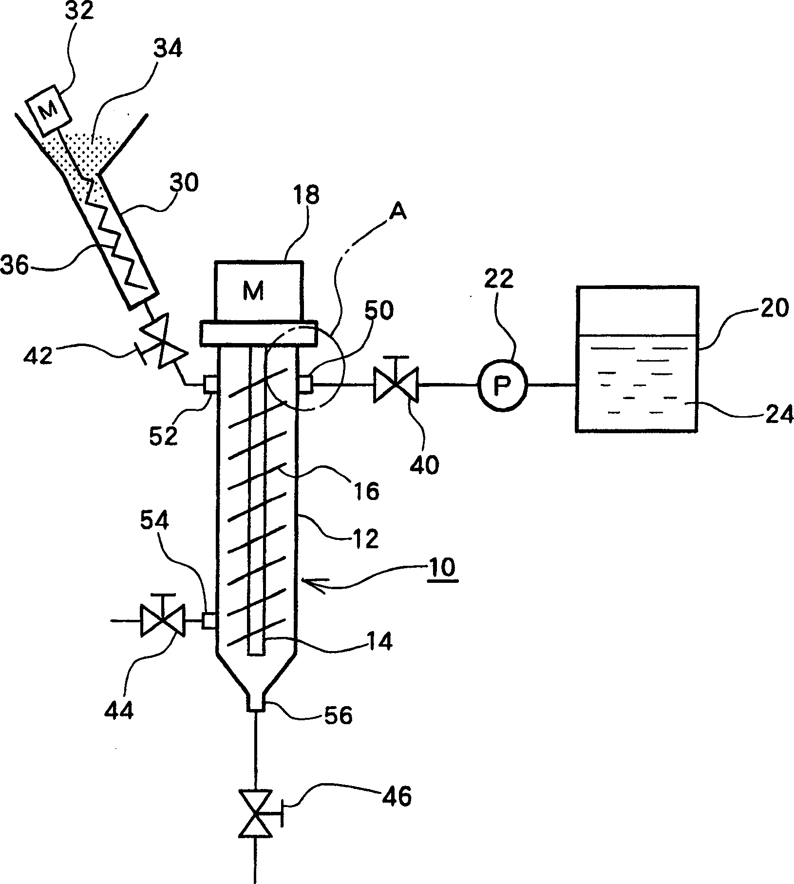
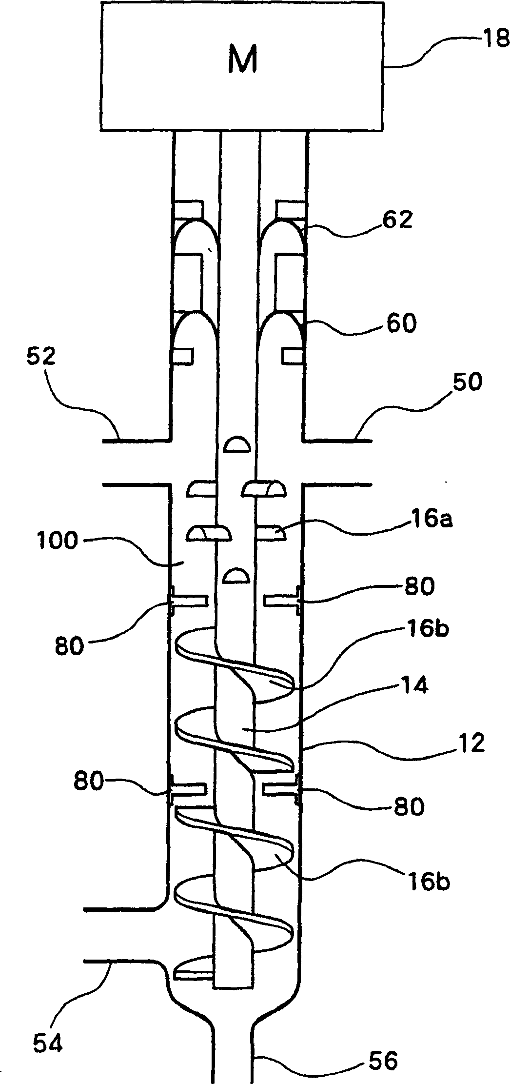
[0059] like figure 1 As shown, the powder and liquid stirring and mixing device 10 of the present embodiment (hereinafter referred to as "stirring and mixing device 10") includes a housing 12 with a flow path for fluid circulation inside, and a stirring body is provided inside the housing 12. , the stirring body is composed of a shaft portion 14 connected to a motor 18 as a vibration source and stirring blades 16 installed around the shaft portion 14 .

[0060] Further, a powder introduction port 52 for introducing powder 34 into the case 12 and a liquid introduction port 50 for introducing liquid 24 into the case near the powder introduction port 52 are provided on the upper portion of the case 12 . In this way, it is possible to further suppress the occurrence of secondary aggregation due to contact between the supplied powder and the liquid.

[0061] Furthermore, the liquid introduction port 50 is connected to the liquid storage tank 20 through the valve 40 and the pump 22...

Embodiment 2

[0067] And, in another embodiment, in figure 1 In the stirring and mixing device shown, the supply port 56 is used to replace the above-mentioned liquid inlet 50, and the pump 22 and the liquid storage tank 20 are connected through the valve 46. The pipe 30 is connected, and then, the liquid inlet 50 of Embodiment 1 is used as a discharge port, so that the mixture of liquid and powder is sent to the outside. Except for the above structure, other structures are the same as those of the above embodiment. For the same structure, same symbols, so their descriptions are omitted.

[0068] As in this embodiment, by introducing the powder 34 and the liquid 24 into the housing 12 from the lower side, vibrating and agitating against gravity, thereby further increasing the amount of turbulence in the housing 12, for example, suitable for uniform stirring of slurry or high viscosity mixtures.

Embodiment 3

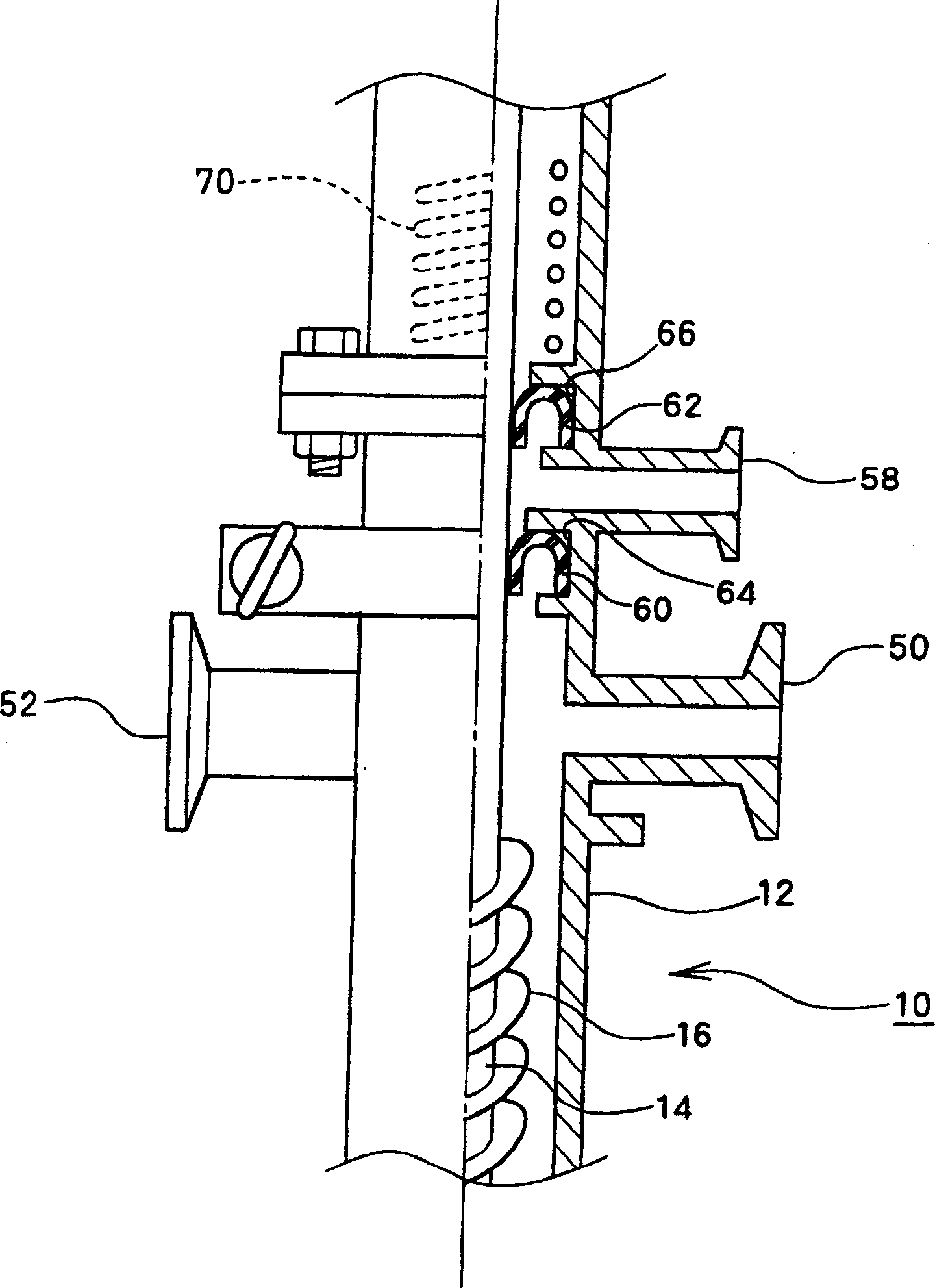
[0070] In another embodiment, in figure 1 In the stirring and mixing device shown, the figure 2 supply port 58 shown in place of figure 1 The illustrated liquid introduction port 50 has the same structure as that of the above-mentioned device except that, and therefore, the same symbols are used for the same structures, and their descriptions are omitted.

[0071] In order to prevent fluid from intruding into the motor as a vibration source for vibrating the stirring body from the internal stirring and mixing part, the housing 12 forms a double sealing structure. That is, if figure 2 As shown, an inverted U-shaped sealing member 60 is installed near the stirring and mixing part by a sealing fastener 64. On the other hand, an inverted U-shaped sealing member 62 is installed near the coil near the motor by using a sealing fastener 66. Form a double sealing structure. One end of the inverted U-shaped seals 60 and 62 is fixed by the above-mentioned seal fasteners 64 and 66 ,...


PUM


Abstract

An apparatus for agitation mixing comprises a casing (12) including a flow channel through which fluid passes, an agitation body consisting of a shaft (14) installed in the casing (12) and connected to a motor (18) and an agitation blade (16) mounted on the perimeter of the shaft (14), a powder inlet (52) attached to the casing (12) to feed a powder (34) into the casing (12), a liquid inlet (50) attached to the casing (12) in the vicinity of the powder inlet (52) to feed a liquid (24) into the casing (12), a powder inlet duct (30) connected to the powder inlet (52), and an introducer (36) placed in the powder inlet duct (30) and connected to a motor (32).

Description

technical field [0001] The invention relates to a stirring and mixing device and a stirring and mixing method, in particular to a highly versatile powder and liquid stirring and mixing device and a stirring and mixing method. Background technique [0002] Generally, powder in liquid is produced when liquid is added to powder and mixed, when powder is added to liquid and mixed, and when only powder and liquid are added and mixed at the same time. Secondary agglomerates of particles (so-called agglomerates) and it is known that redispersing secondary agglomerates that have occurred into a liquid will be very difficult. In particular, this phenomenon is remarkable in the case of mixing powder into a high-viscosity liquid. [0003] Therefore, in recent years, devices and methods for uniformly mixing powder and liquid without causing secondary aggregation have been proposed. [0004] In JP 11-19495, JP 2001-62273, and JP 2002-166154, a continuous mixing device for liquid and po...

Claims


Application Information

Patent Timeline
Patent Type & Authority Applications(China)
IPC IPC(8): B01F1/00B01F3/12B01F5/10B01F7/00B01F11/00B01F15/00
CPCB01F2003/0028B01F2001/0094B01F1/0011B01F3/1271B01F15/0251B01F3/1221B01F13/1044B01F2013/1083B01F11/0082B01F5/10B01F3/1228B01F15/00019B01F7/0045B01F7/00391B01F2015/00084B29B7/94B29B7/603B29B7/14B29B7/16B29B7/244B29B7/401B29B7/421B29B7/428B29B7/422B29B7/429B01F21/504B01F23/023B01F21/10B01F23/54B01F23/59B01F23/53B01F25/50B01F27/114B01F27/115B01F31/441B01F33/8305B01F35/145B01F33/83612B01F2035/351B01F35/71775
Inventor 谷口彻
Owner REICA KOGYO kk
Why Eureka
Try Eureka