Switch mechanism and machin having said switch mechanism

A switching mechanism and machine technology, applied in the direction of electrical switches, magnetic/electric field switches, electrical components, etc., can solve the problem of inconvenient hand-held movement and so on

Inactive Publication Date: 2004-05-19
OVAL CORP
View PDF0 Cites 6 Cited by
  • Summary
  • Abstract
  • Description
  • Claims
  • Application Information

AI Technical Summary

Problems solved by technology

Even if the permanent magnet does not pass through an area that co

Method used


Image

  • Switch mechanism and machin having said switch mechanism
  • Switch mechanism and machin having said switch mechanism
  • Switch mechanism and machin having said switch mechanism

Examples


Embodiment Construction

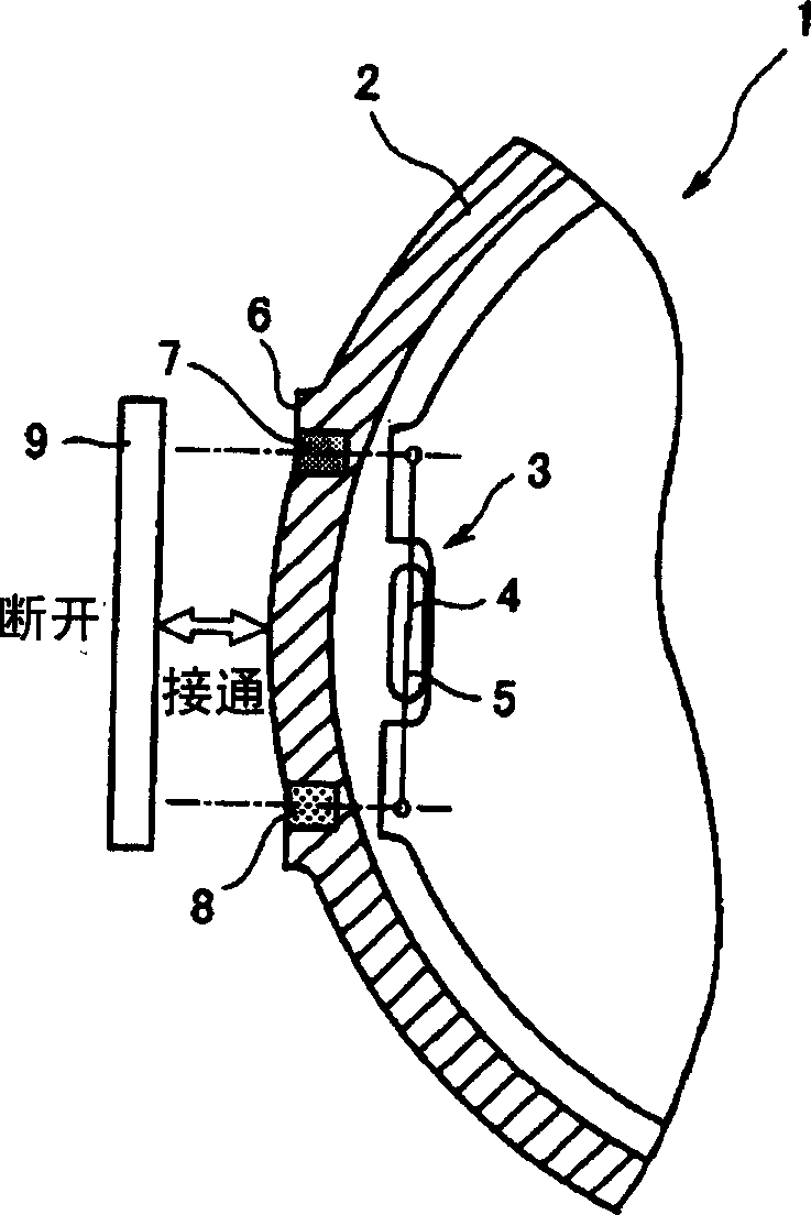
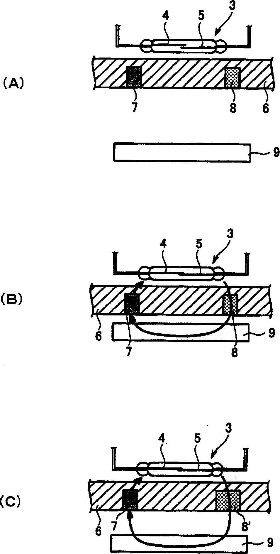
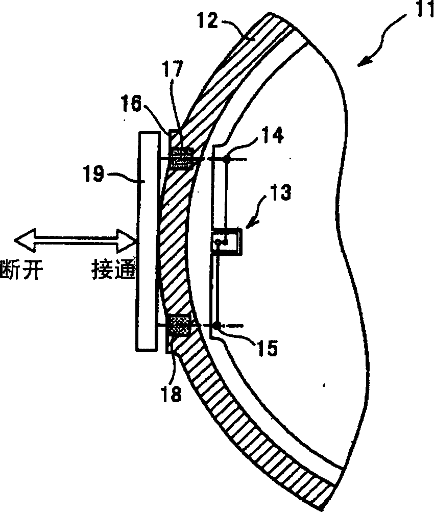
[0026] The switch mechanism of the present invention is a mechanism in which a magnetic field sensing device for sensing a predetermined magnetic field is provided inside a device, and the operation of the device is switched by the magnetic field sensing device. In the present invention, the term "apparatus" includes a switch device for remote operation of certain devices, in addition to an apparatus in which a user switches operations while looking at an operation display unit. In addition, in the present invention, the so-called magnetic field induction device is a device that induces a predetermined magnetic field by magnetic induction, and is not exposed outside the device, but is disposed through a partition of the device. Some examples of the present invention will be described below, but the present invention is not limited to the following examples.

[0027] First, as an embodiment of the present invention, an embodiment using a reed contact switch as a magnetic field ...


PUM


Abstract

To provide a switching mechanism of which an equipment need not be made large in size nor complicated, and much less, a permanent magnet which may affect a sensor or the like need not be carried about for operation of the equipment. Switching of operation in the equipment 1 is carried out by a reed switch 3 provided inside the equipment 1 sensing a given magnetic field. The reed switch 3, provided with reed relays 4, 5, senses the given field base on magnetic induction and closes contacts of the reed relays 4, 5. The switching mechanism arranges a permanent magnet 7 and a ferromagnet 8 inside the equipment 1, in a state having the reed switch 3 not sense the given field, that is, so as not to induce magnetic induction. As a user brings another ferromagnet (a ferromagnet for operation) 9 near the permanent magnet 7 or the ferromagnet 8 from outside the equipment 1, the magnetic induction is induced to the reed switch 3 to close the contacts of the reed relays 4, 5, which makes it possible to operate the equipment. (C)2004,JPO.

Description

technical field [0001] The present invention relates to a switch mechanism and a machine equipped with the switch mechanism, more specifically, a switch mechanism which is especially suitable for being installed on a machine installed outdoors to switch the operation of the machine through a partition of the machine, and a machine with the switch mechanism machine. Background technique [0002] The operation of setting various modes or parameters on various machines is usually performed through an operation panel or a single switch. When the machine is installed outdoors where waterproof and explosion-proof are required, the machine can be operated by switching the switch inside the machine through the next door of the machine. [0003] Image 6 It is a schematic diagram of an example of a configuration of a conventional switch mechanism for outdoor equipment. exist Image 6 Among them, the description of the symbols is as follows: 41 represents the machine, 42 represents ...

Claims


Application Information

Patent Timeline
IPC IPC(8): H01H36/00
Inventor 早川修
Owner OVAL CORP
Why Eureka
Try Eureka