Method and device for controlling ink supply amount for printer

A control method and technology for printing presses, which are applied to general parts of printing machinery, printing presses, printing and other directions, and can solve the problems of long operation time, waste of printing materials, and increase of waste paper volume.

Inactive Publication Date: 2004-07-14
KOMORI CORP
View PDF1 Cites 6 Cited by
  • Summary
  • Abstract
  • Description
  • Claims
  • Application Information

AI Technical Summary

Problems solved by technology

In this case, the amount of waste paper is increased, the operation time is long, the burden on the operator is increased, printing materials are wasted, and the operation efficiency is reduced

Method used


Image

  • Method and device for controlling ink supply amount for printer
  • Method and device for controlling ink supply amount for printer
  • Method and device for controlling ink supply amount for printer

Examples


no. 1 example

[0028] [First embodiment: manual method]

[0029] As a first embodiment, a method (manual method) of causing an operator to instruct execution or non-execution of "intermittent stop+correction" according to his own judgment will be described below.

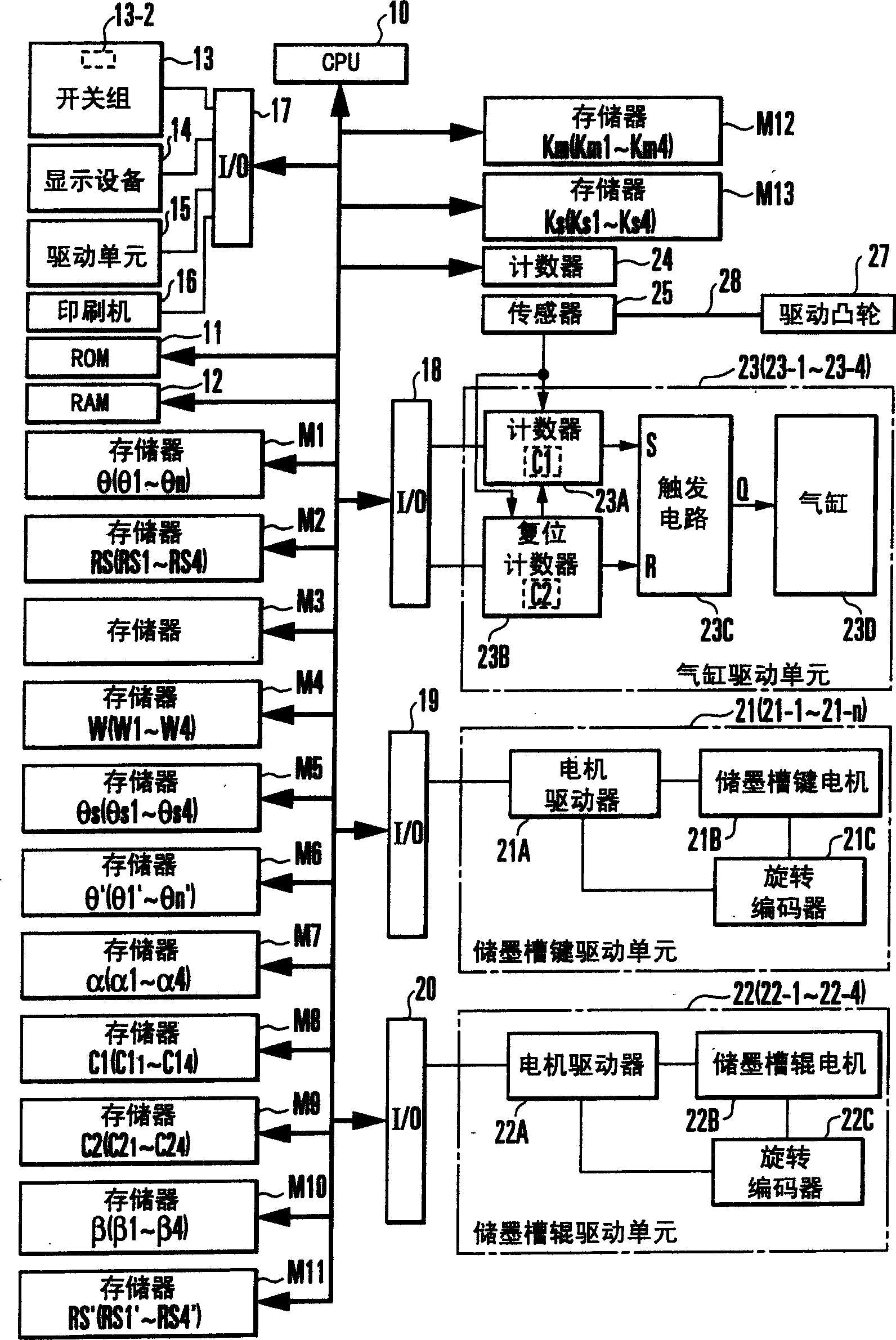
[0030] figure 1 An ink supply amount control device for a printing press according to a first embodiment of the present invention is shown. refer to figure 1 , reference numeral 10 represents a CPU (Central Processing Unit); 11 represents a ROM (Read Only Memory); 12 represents a RAM (Random Access Memory); 13 represents a switch group including a correction button 13-1; 14 represents a display device; 16 represents a printer; and 17 to 20 represent input / output interfaces (I / O). Reference symbols M1 to M11 denote memories storing various data. Reference numeral 21 denotes a sump key driving unit; 22, a sump roller driving unit; and 23, a supply stop cylinder driving unit.

[0031] The CPU 10 obtains various input informati...

no. 3 example

[0116] In the second embodiment described above, the ratio γ of the small image portion number Km to the total number Kn of ink tank keys in the printing unit 9 is obtained. The ratio γ can be obtained as a ratio of the number Km of small image parts not to the total number Kn of ink reservoir keys, but to the number Kx of ink reservoir keys used for printing. The number Kx of ink tank keys used for printing can be obtained by, for example, method ① or ② to be described below. In methods ① and ②, the number Km of the small image portion is equal to the number of ink reservoir keys whose opening ratio is greater than zero and smaller than the determined value θs (0<θ<θs) of the small image portion.

[0117] [①Method of using the input paper size as preset information]

[0118] When the total number n of ink tank keys is an even number, calculate paper size / ink tank key width / 2=a. The obtained number Kx of ink tank keys to be used for printing is Kx=(integer value obtained by ...

no. 4 example

[0137] [Fourth Embodiment: Automatic Method]

[0138] In the automatic method described in the first embodiment, the opening degree ratio setting value θ of the ink sump key 4 or the supply amount setting value RS of the ink sump roller 3 is corrected. In the automatic method according to the fourth embodiment, instead of correcting these values, the actual value θpv of the opening ratio of the ink tank key 4, or the actual value RSpv of the supply amount of the ink tank roller 3 is corrected.

[0139] in accordance with Figure 10 In the ink supply amount control apparatus of the fourth embodiment shown in , the number of ink tank keys whose actual value θpv of the opening ratio of the ink tank key is smaller than the small image portion determination value θs is counted. When the count number of the ink tank key is larger than Ks, it is determined that the number of ink supply operations must be reduced.

[0140] refer to Figure 10 , replace with a potentiometer 21D fi...


PUM


Abstract

In an ink supply amount control method for a printing press, the number of ink fountain keys whose gap amount with respect to an ink fountain roller falls within a predetermined range is counted. On the basis of the count value, the swing operation of an ink ductor roller which is arranged in an ink supply path and swings in synchronism with rotation of the printing press is controlled. Ink is supplied from the gap between the plurality of ink fountain keys and the ink fountain roller to the ink supply path in accordance with rotation of the ink fountain roller at the time of printing. The ink is supplied to a printing plate attached to a plate cylinder through the ink supply path by the swing operation of the ink ductor roller. An ink supply amount control apparatus and a printing press are also disclosed.

Description

technical field [0001] The present invention relates to ink supply control of printing presses, and more particularly, to a system capable of suppressing any density variation in prints printed with small image areas by intermittently stopping the oscillation of the ink supply roller (ink supply operation). Ink supply control method and device. Background technique [0002] The amount of ink supplied to the printing plate in a printing press is generally controlled by the amount of gap between the ink reservoir key and the ink reservoir roller. Figure 14 Main parts of an ink supply device (ink roller) provided in a printing unit of each color (ink color) in a rotary printing press are shown. refer to Figure 14 , Ink storage tank 1 stores ink 2. The ink reservoir roller 3 supplies ink from the ink reservoir 1 to the ink supply path. A plurality of ink sump keys 4 ( 4 - 1 to 4 - n ) are arranged side by side along the axial direction of the ink sump roller 3 . An ink deli...

Claims


Application Information

Patent Timeline
Patent Type & Authority Applications(China)
IPC IPC(8): B41F31/02B41F31/04B41F31/14
CPCB41F31/04B41F31/14
Inventor 平野正大富田俊一
Owner KOMORI CORP
Why Eureka
Try Eureka