Service providing equipment by using user as centre and its method
A technology for service providers and users, applied in the direction of using stored programs for program control, special data processing applications, memory address/allocation/relocation, etc. question
- Summary
- Abstract
- Description
- Claims
- Application Information
AI Technical Summary
Problems solved by technology
Method used
Image

Examples
Embodiment Construction
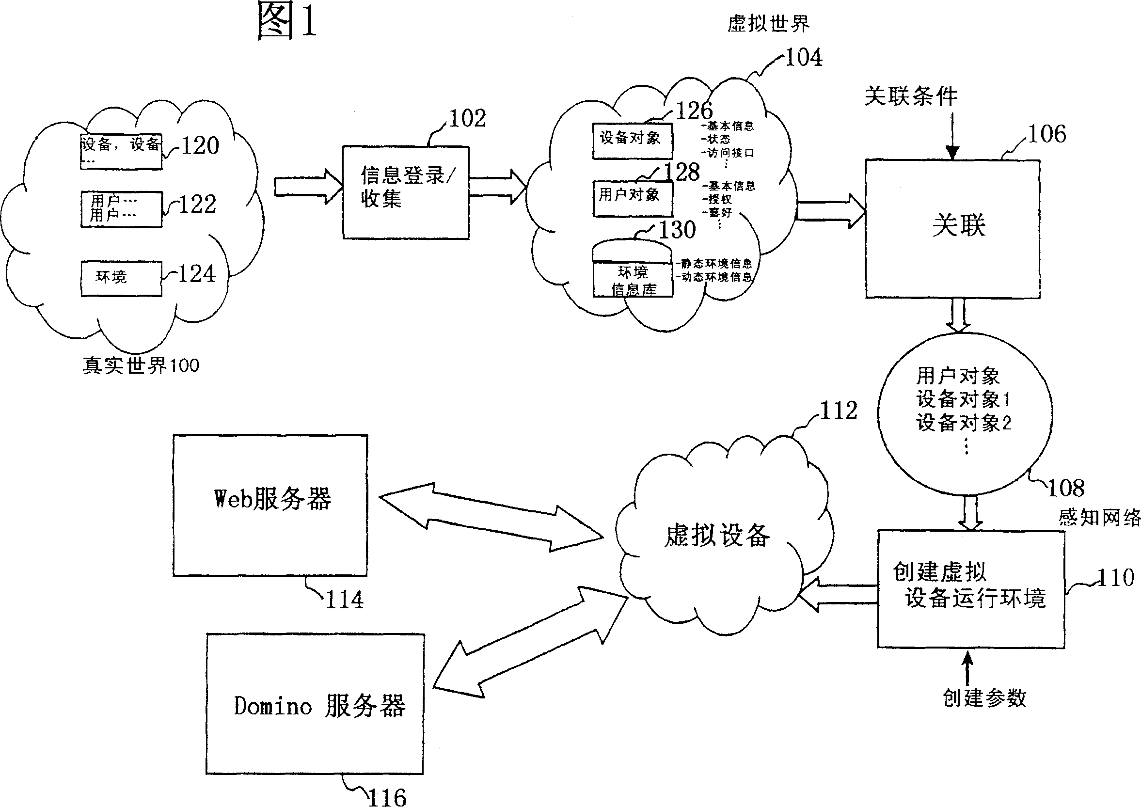
[0041] As shown in FIG. 1, this figure shows a conceptual diagram of a service providing system according to the present invention. The service providing system of the present invention constructs virtual equipment for each user according to physical objects in the real world, such as users and physical equipment; and the service providing system of the present invention can also use the information of the environment around each user, mainly The environmental information related to the user in space is collected. The user accepts the service of the service provider through the constructed virtual device. The users mentioned in the invention include not only people in the real world, but also entities such as animals. The equipment referred to in the present invention includes all physical equipment that can provide communication services for users.
[0042] The process in Figure 1 is briefly described below.
[0043] First, physical objects of the real world 100, such as u...
PUM
 Abstract
Description
Claims
Application Information
 - Generate Ideas
- Intellectual Property
- Life Sciences
- Materials
- Tech Scout
- Unparalleled Data Quality
- Higher Quality Content
- 60% Fewer Hallucinations
Browse by: Latest US Patents, China's latest patents, Technical Efficacy Thesaurus, Application Domain, Technology Topic, Popular Technical Reports.
© 2025 PatSnap. All rights reserved.Legal|Privacy policy|Modern Slavery Act Transparency Statement|Sitemap|About US| Contact US: help@patsnap.com