Angular position pick up for measuring high linear flux density

A technology for measuring sensors and magnetic flux density, which is applied in the direction of using electric/magnetic devices to transfer sensing components, measuring devices, and converting sensor outputs, etc., which can solve problems such as large computing burdens

Inactive Publication Date: 2004-08-11
DENSO CORP
View PDF1 Cites 26 Cited by
  • Summary
  • Abstract
  • Description
  • Claims
  • Application Information

AI Technical Summary

Problems solved by technology

Determining the absolute angular position of the axis of rotation requires extensive computation of trigonometric functions and / or the use of mappings, which poses the problem of an undesirably large computational burden on the system

Method used


Image

  • Angular position pick up for measuring high linear flux density
  • Angular position pick up for measuring high linear flux density
  • Angular position pick up for measuring high linear flux density

Examples


Embodiment Construction

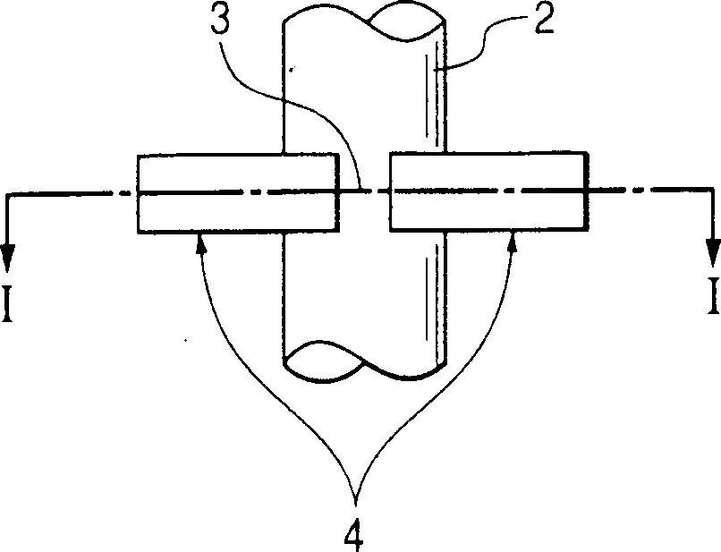
[0068] Referring to the accompanying drawings, wherein the same reference numerals refer to the same parts in the accompanying drawings, especially Fig. 1 (a) and Fig. 1 (b), they represent the angular position detector 1 according to the first embodiment of the present invention .

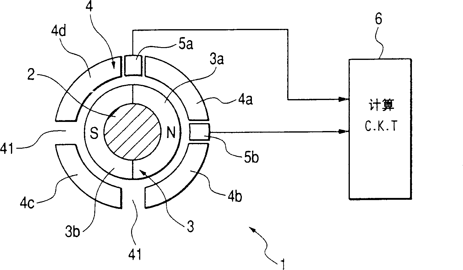
[0069] The angular position detector 1 mainly includes an angular position sensor installed on the periphery of the rotating shaft 2 and an angular position calculation circuit 6 . The angular position calculation circuit 6 is designed to determine the angular position of the rotary shaft 2 using the output of the angular position sensor.

[0070] The angular position sensor includes a magnet 3 made of hard magnetic material, a yoke 4 made of soft magnetic material, and a magnetic sensor 5 for measuring magnetic flux density.

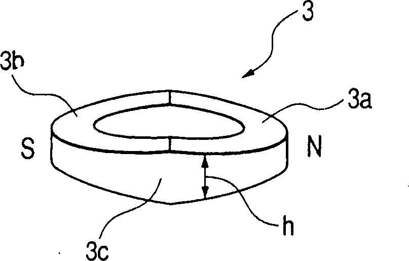
[0071] The magnet 3 is annular and fixed on the periphery of the rotating shaft 2 . The magnet 3 is composed of two semicircular parts: one has an N pole 3a, and the othe...


PUM


Abstract

An angular position sensor is provided which is designed to an angular position of a rotary shaft. The angular position sensor has a magnet affixed to the rotary shaft. The magnet has an N-pole and an S-pole and is so geometrically shaped as to produce magnetic flux which is substantially uniform in amount within a range extending around each of centers of the N-pole and the S-pole. This improves the linearity of a change in sensor output upon rotation of the rotary shaft.

Description

technical field [0001] This invention relates generally to angular position sensors for measuring the angular position of rotating parts, and more particularly to an improved structure for such angular position sensors designed to sense a more linear magnetic flux density. Background technique [0002] A typical angular position sensor for measuring the angular position of a rotating shaft consists of a ring magnet, a yoke and a plurality of magnetic sensors. The ring magnet has N poles and S poles arranged in its circumferential direction. the periphery of the magnet. The yoke has radial grooves formed therein, the radial grooves forming an air gap. Magnetic sensors are arranged in the air gaps and are used to measure the magnetic flux density in these air gaps. For example, US Patent No. 5,528,139 (corresponding to Japanese Patent No. 2842482) issued to Oudet et al. on June 18, 1996 discloses this type of angular position sensor. [0003] The N pole and the S pole of th...

Claims


Application Information

Patent Timeline
Patent Type & Authority Applications(China)
IPC IPC(8): G01B7/30B62D5/00B62D5/04G01B7/00G01D5/12G01D5/14G01D5/16G01D5/245
CPCG01D5/145B62D15/021G01B7/30
Inventor 深谷繁利武田宪司中根直树今村哲夫
Owner DENSO CORP
Why Eureka
Try Eureka