Sphygmomanometer

A sphygmomanometer and cuff technology, applied in the field of sphygmomanometers, can solve the problem that the volume structure is not suitable for family use, etc., and achieve the effect of suppressing the error of determination accuracy

Inactive Publication Date: 2004-09-01
MATSUSHITA ELECTRIC WORKS LTD
View PDF1 Cites 20 Cited by
  • Summary
  • Abstract
  • Description
  • Claims
  • Application Information

AI Technical Summary

Problems solved by technology

[0005] In addition, although there is an automatic sphygmomanometer with an oscillometric measurement method equipped with an automatic winding mechanism in order to eliminate the deviation caused by the winding of the subject, it is not suitable for home use in terms of size and structure.

Method used


Image

  • Sphygmomanometer
  • Sphygmomanometer
  • Sphygmomanometer

Examples


Embodiment Construction

[0051] Hereinafter, embodiments of the present invention will be described in detail with reference to the drawings.

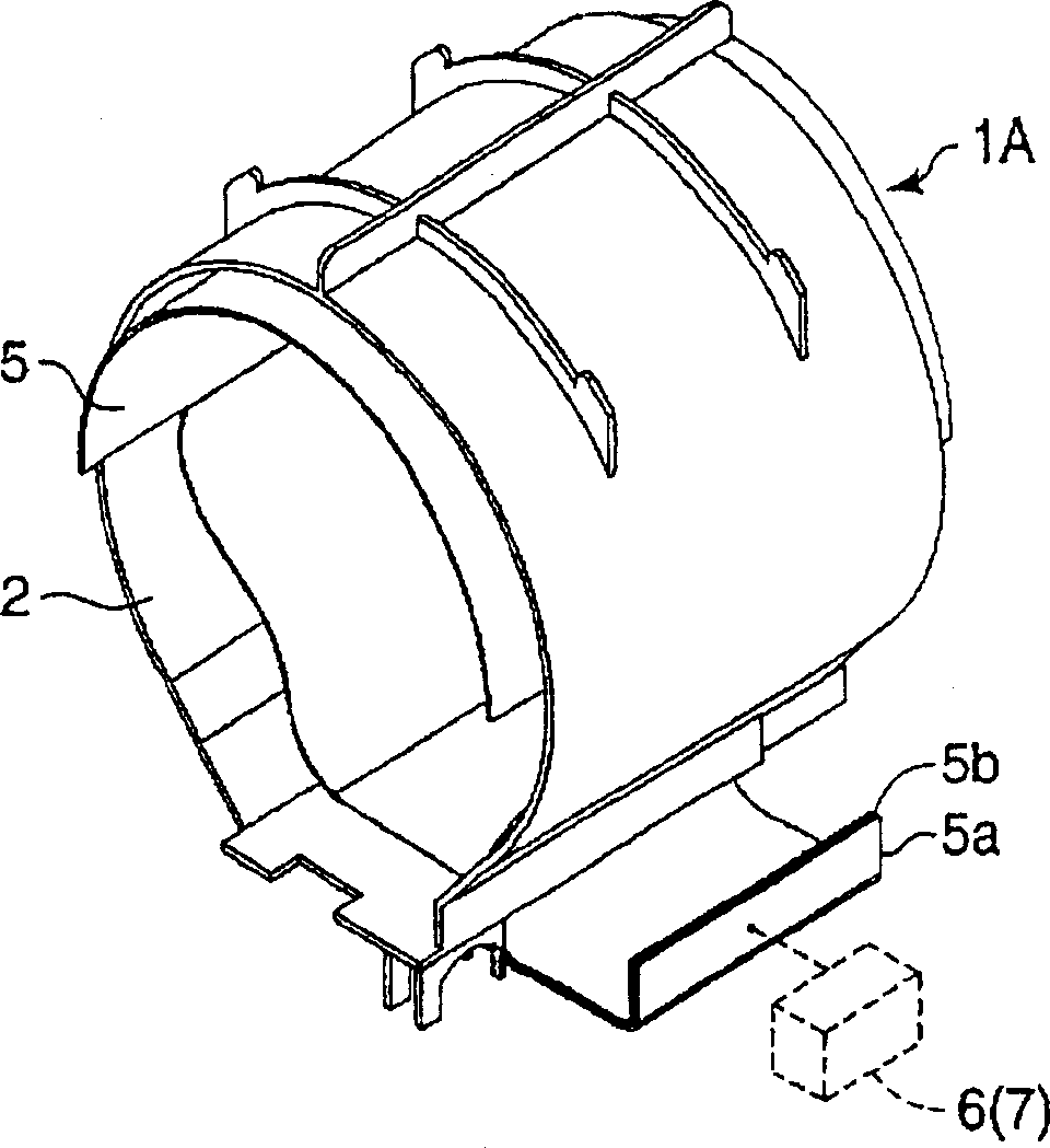
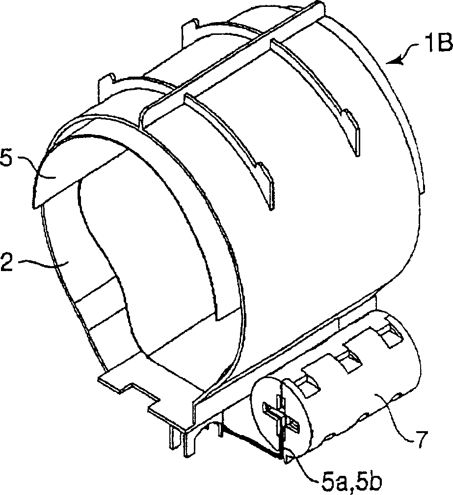
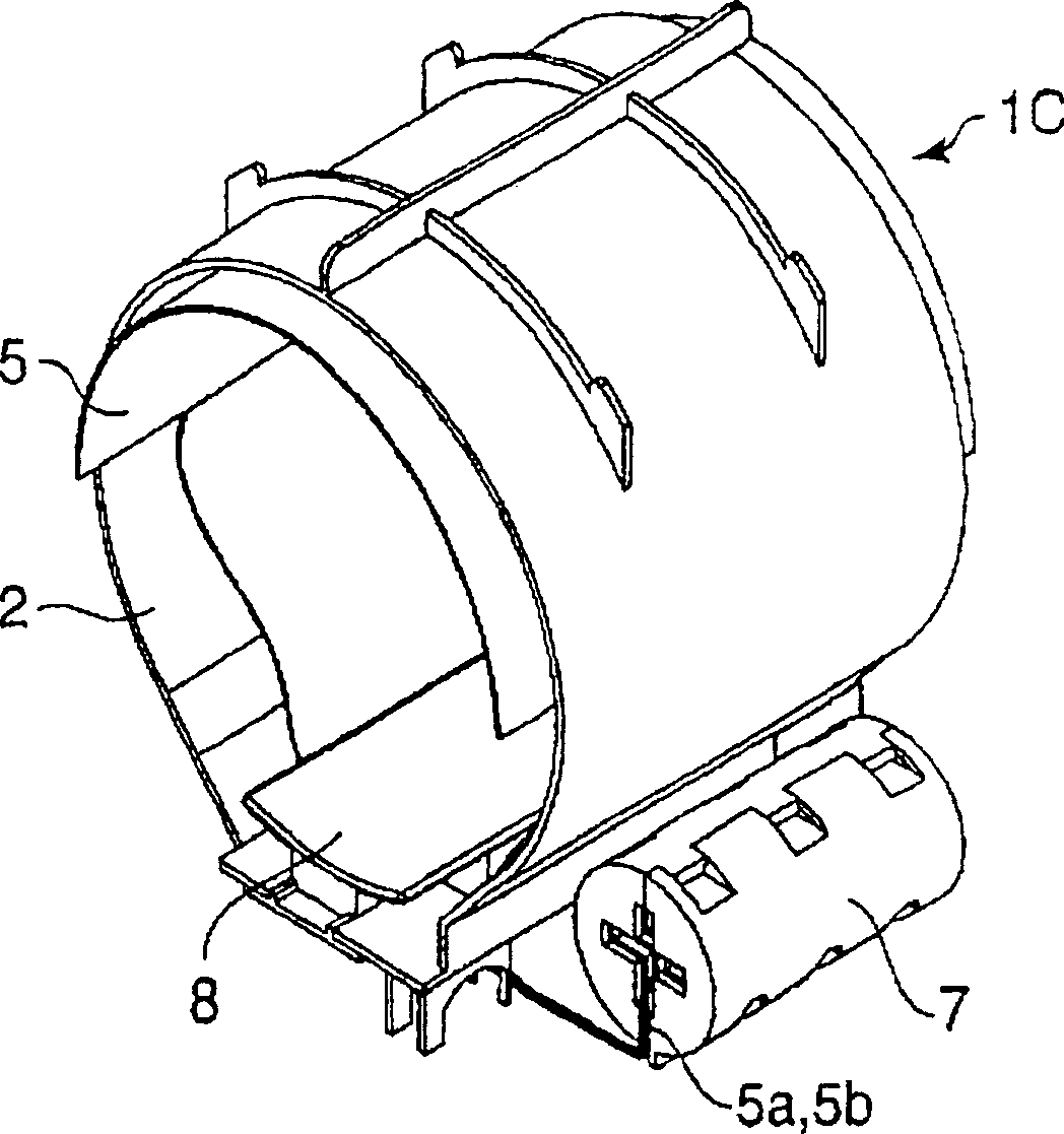
[0052] figure 1 It is a perspective view of the limb insertion sleeve 2 of the sphygmomanometer 1A of the first embodiment.

[0053] The sphygmomanometer 1A consists of a limb insertion sleeve 2 and a sphygmomanometer main body 3 (refer to Figure 7 )constitute.

[0054] The sleeve 2 for the above-mentioned limb insertion is as Figure 5As in the section shown in (a), it is composed of a cylindrical rigid body into which the subject's arm or wrist 4 can be inserted, and a pull-out opening 2a is formed at the lower part thereof.

[0055] On the inner surface of the above-mentioned limb insertion sleeve 2, the cuff is supported in a manner to maintain a cylindrical shape, and the two ends 5a, 5b of the cuff 5 are drawn in the same direction from the above-mentioned pulling port 2a to the outside [ Figure 5 the right side in (a)] and pull it out.

[0056] A...


PUM


Abstract

This hemadynamometer 1A has an automatic rolling up mechanism 6 for a cuff band 5. At the same time, with the automatic rolling up mechanism 6, both end parts 5a and 5b of the cuff band 5 which is held on the internal surface of a biological inserting block 2 are connected, simultaneously roll up both end parts 5a and 5b of the cuff band 5. Thus, the rolling up time of the cuff band 5 is shortened, and the rolling up diameter can be reduced. To provide a hemadynamometer which is compact and optimal for home use.

Description

technical field [0001] The present invention relates to a small sphygmomanometer most suitable for home use. Background technique [0002] Conventionally, when using the oscillometric method to measure the blood pressure value of the human body (arm, wrist), it was necessary to measure in advance with a certain Strength A cuff (cuff band) is wrapped around the measurement site of the subject so that the volume of the air pocket of the cuff becomes a constant value. [0003] However, among cheap household blood pressure monitors, the cuff-separate type that requires the subject to wind the cuff around the measurement site is often used (for example, refer to Patent Document 1). Therefore, measurement accuracy is likely to be affected depending on how the subject's cuff is wound up. [0004] Patent Document 1: Japanese Unexamined Patent Publication No. 7-124127 [0005] In addition, there is an automatic sphygmomanometer with an oscillometric measurement method equipped wit...

Claims


Application Information

Patent Timeline
Patent Type & Authority Applications(China)
IPC IPC(8): A61B5/022
Inventor 文室晋一冈田浩一汤浅毅
Owner MATSUSHITA ELECTRIC WORKS LTD
Why Eureka
Try Eureka