Image generating apparatus

a technology of image generating apparatus and receiving hole, which is applied in the direction of printing mechanism, thin material processing, printing, etc., can solve the problems of inability to precisely perform torque control, inability to maintain slip torque in manufacturing, and inability to maintain pressing force constant, so as to ensure the stability of the reel member, increase the length of the bearing, and ensure the effect of rotatability

Inactive Publication Date: 2010-07-27
FUNAI ELECTRIC CO LTD
View PDF14 Cites 0 Cited by
  • Summary
  • Abstract
  • Description
  • Claims
  • Application Information

AI Technical Summary

Benefits of technology

[0018]In the image generating apparatus according to the aforementioned aspect, the spring member is preferably an annular coil spring, and the spring member is preferably press-fitted with the inner peripheral surfaces of the fragment portions of the reel member in a state reduced in coil diameter from an unloaded condition. According to this structure, pressing force for outwardly spreading the fragment portions of the reel member can be easily obtained through restoring force (elastic energy) of the coil spring restored to the unloaded condition from the state press-fitted with the inner peripheral surfaces of the fragment portions of the reel member.
[0031]In the aforementioned structure further comprising the chassis and the bracket member, the receiving hole of the chassis is preferably formed by burring to have an inner side surface cylindrically protruding from the surface of the chassis. According to this structure, the length of the inner side surface of the receiving hole can be increased due to the burring, thereby more reliably rotatably supporting the reel member with respect to the chassis.

Problems solved by technology

Depending on the material of the inner race, therefore, the elastic portions of the torque limiting members may conceivably be so aged with time that the pressing force cannot be kept constant.
In this case, slip torque set in manufacturing cannot be maintained, whereby torque control cannot be precisely performed.
When the torque limiter according to Japanese Patent Laying-Open No. 2005-344858 is applied to a take-up reel of an image generating apparatus comprising a driving source transporting an ink sheet of an ink sheet cartridge and the take-up reel transmitting the driving force of the driving source to a take-up bobbin of the ink sheet cartridge and taking up the ink sheet on the take-up bobbin, therefore, the take-up reel cannot perform proper torque control on the take-up bobbin upon action of the torque limiter function.
Thus, the torsion coil spring must apply limited clamping force to the small contact regions, whereby it is conceivably difficult for the torque limiter to stably operate.
When the torque limiter according to Japanese Patent Laying-Open No. 7-269589 is applied to the take-up reel of the image generating apparatus comprising the driving source transporting the ink sheet of the ink sheet cartridge and the take-up reel transmitting the driving force of the driving source to the take-up bobbin of the ink sheet cartridge and taking up the ink sheet on the take-up bobbin, therefore, the ink sheet cannot be stably taken up on the take-up bobbin with proper tensile force.
Consequently, the elastic force of the coil spring is conceivably aged with time due to repetitive heat generation and cooling.
In this case, slip torque set in manufacturing cannot be maintained, whereby torque control cannot be precisely performed.
When the torque limiter according to Japanese Patent Laying-Open No. 5-106641 is applied to the take-up reel of the image generating apparatus comprising the driving source transporting the ink sheet of the ink sheet cartridge and the take-up reel transmitting the driving force of the driving source to the take-up bobbin of the ink sheet cartridge and taking up the ink sheet on the take-up bobbin, therefore, the take-up reel cannot perform proper torque control on the take-up bobbin upon action of the torque limiter function.
Consequently, the elastic force of the coil spring is conceivably aged with time due to repetitive heat generation and cooling.
In this case, slip torque set in manufacturing cannot be maintained, whereby torque control cannot be precisely performed.
When the bidirectional torque limiter described in Japanese Patent Laying-Open No. 7-229524 is applied to a take-up reel of an image generating apparatus comprising a driving source transporting an ink sheet of an ink sheet cartridge and the take-up reel transmitting the driving force of the driving source to a take-up bobbin of the ink sheet cartridge and taking up the ink sheet on the take-up bobbin, therefore, the take-up reel cannot perform proper torque control on the take-up bobbin upon action of the torque limiter function, similarly to the case of the torque limiter described in Japanese Patent Laying-Open No. 5-106641.
Thus, the close-coiled spring must apply limited clamping force to the small contact regions, whereby it is conceivably difficult for the ribbon take-up mechanism to stably operate.

Method used


Image

  • Image generating apparatus
  • Image generating apparatus
  • Image generating apparatus

Examples


Embodiment Construction

[0051]An embodiment of the present invention is now described with reference to the drawings.

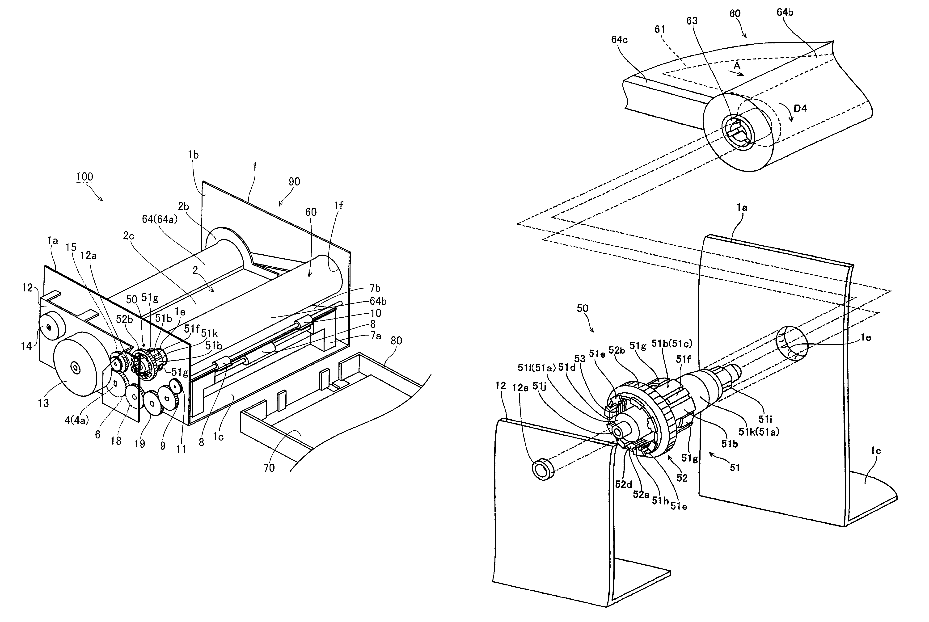
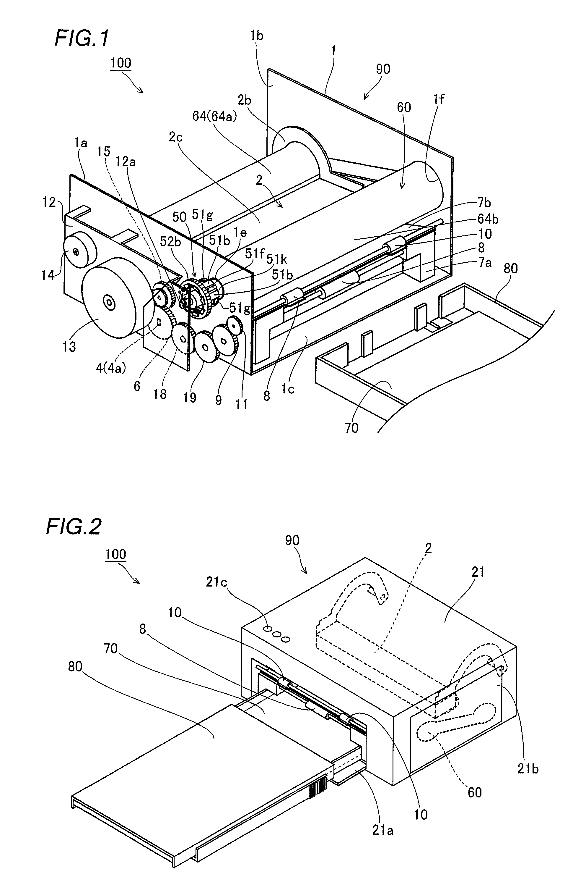
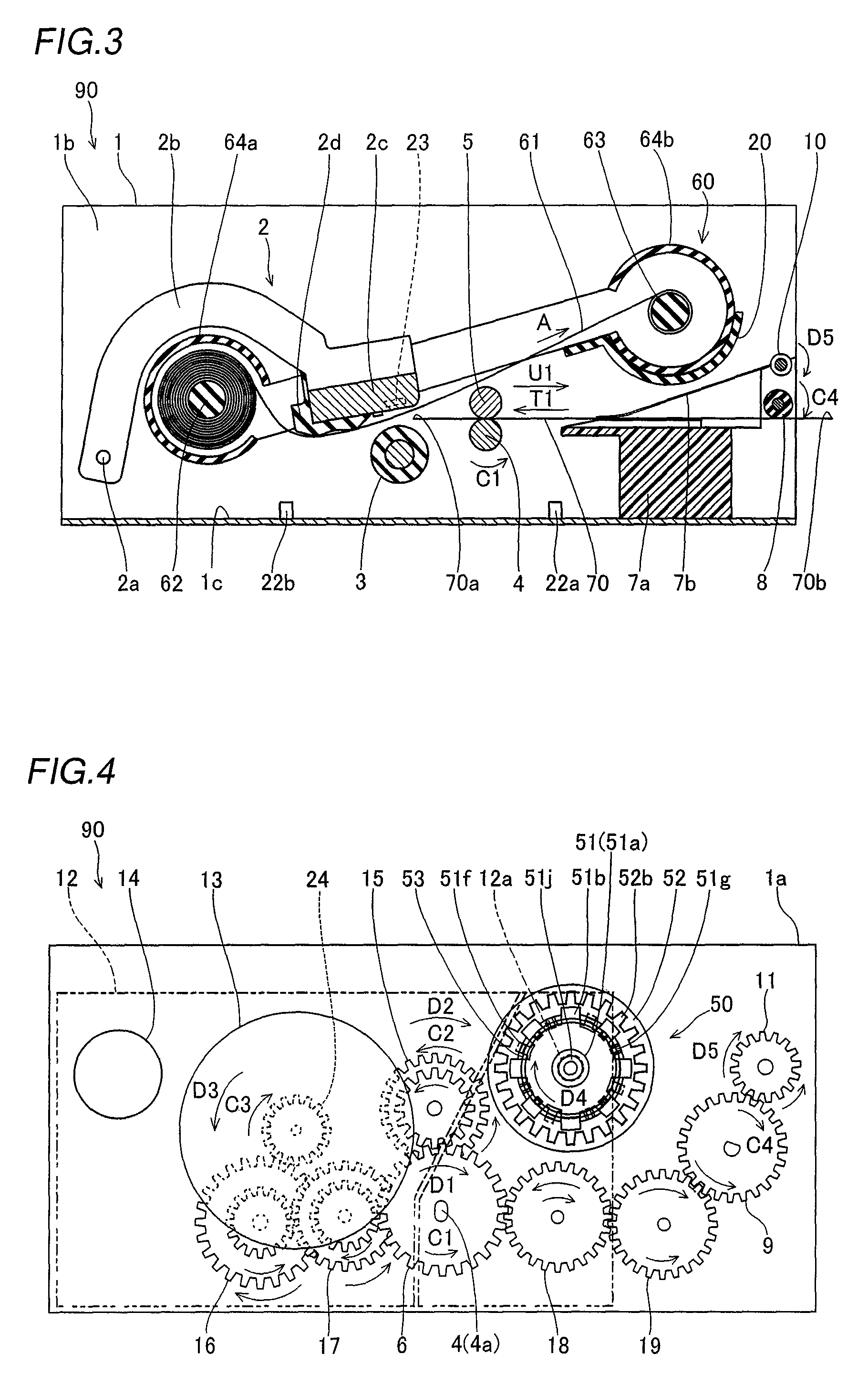
[0052]First, the structure of a sublimatic printer 100 according to the embodiment of the present invention is described with reference to FIGS. 1 to 5. According to this embodiment, the present invention is applied to the sublimatic printer 100 employed as an exemplary image generating apparatus.

[0053]As shown in FIG. 1, a printer body 90 of the sublimatic printer 100 according to the embodiment of the present invention comprises a chassis 1 of metal, a print head 2 for printing, a platen roller 3 (see FIG. 3) opposed to the print head 2, a feed roller 4 (see FIG. 3) of metal, a press roller 5 (see FIG. 3) of metal pressing the feed roller 4 with prescribed pressing force, a feed roller gear 6, a lower paper guide 7a of resin, an upper paper guide 7b of resin, a paper feed roller 8 of rubber, a paper feed roller gear 9, a paper discharge roller 10 of rubber, a paper discharge roller gear 11...


PUM


Abstract

An image generating apparatus capable of stably taking up an ink sheet on a take-up bobbin with proper tensile force by performing proper torque control on the take-up bobbin is obtained. This image generating apparatus comprises a driving source transporting an ink sheet of an ink sheet cartridge and a take-up reel transmitting the driving force of the driving source to a take-up bobbin of the ink sheet cartridge and taking up the ink sheet on the take-up bobbin, while the take-up reel includes a reel member, integrally provided with a plurality of fragment portions concentrically with the rotation axis thereof, engaging with the take-up bobbin, a driving-side gear member fitted with the outer peripheral surfaces of the fragment portions of the reel member and a spring member press-fitted with the inner peripheral surfaces of the fragment portions of the reel member thereby bringing the fragment portions into pressure contact with the driving-side gear member.

Description

BACKGROUND OF THE INVENTION[0001]1. Field of the Invention[0002]The present invention relates to an image generating apparatus comprising a take-up reel taking up an ink sheet on a take-up bobbin.[0003]2. Description of the Background Art[0004]A torque limiter mechanism applied to an image generating apparatus or the like comprising a take-up reel taking up an ink sheet on a take-up bobbin is known in general, as disclosed in each of Japanese Patent Laying-Open Nos. 2005-344858, 7-269589 (1995), 5-106641 (1993), 7-229524 (1995) and 2005-199520, for example.[0005]The aforementioned Japanese Patent Laying-Open No. 2005-344858 discloses a torque limiter comprising a rotating cylindrical housing and an inner race including a plurality of torque limiting members integrally having deflectable elastic portions annularly provided on the outer peripheral surface thereof. In the torque limiter described in Japanese Patent Laying-Open No. 2005-344858, the torque limiting members of the inner r...

Claims


Application Information

Patent Timeline
Patent Type & Authority Patents(United States)
IPC IPC(8): B65H16/06
CPCB41J17/12B41J17/24B65H75/30B65H2701/372
Inventor SAWAI, KUNIO
Owner FUNAI ELECTRIC CO LTD
Why Eureka
Try Eureka