Tensioner with one-way clutch

a one-way clutch and tensioner technology, which is applied in the field of tensioners, can solve the problems of high cost, high labor intensity, and vibration of the tensioner lever, and achieve the effects of reducing the diameter of the spring, simple structure, and easy assembly

Inactive Publication Date: 2009-06-02
TSUBAKIMOTO CHAIN CO
View PDF17 Cites 11 Cited by
  • Summary
  • Abstract
  • Description
  • Claims
  • Application Information

AI Technical Summary

Benefits of technology

[0015]Upon rotation of the lever in said one direction, the diameter of the coil spring is reduced, thereby reducing the outward pressing force exerted by the spring on the cylindrical inner surfaces of the annular members, and upon rotation of the lever in the opposite direction the diameter of the coil spring is increased, thereby increasing the outward pressing force exerted by the spring on the cylindrical inner surfaces of the annular members.
[0020]Because the clutch comprises relatively rotatable first and second annular members, and a coil spring pressing against the inner circumferential surfaces of the annular members, the tensioner can have a very simple structure. Furthermore, the clutch can be easily assembled by inserting the coil spring while rotating the annular members in a direction such that friction between the annular members and the spring causes the diameter of the spring to decrease.
[0021]Where the first annular member of the clutch is a boss formed as a unitary part of the lever body, the structure of the tensioner is very simple, and this version in particular can be advantageously manufactured from synthetic resin. When the outer circumferential surfaces of the annular members of the clutch are flush with each other, a torsion coil spring for biasing the lever can be fitted easily in surrounding, spaced relationship with the annular members so that its coiled portion does not come into contact with the annular members.
[0022]Since the outward force exerted by the spring on the annular members of the clutch increases with rotation of the lever body in one direction and decreases with rotation in the opposite direction, reverse pivoting of the lever can be effectively blocked, and appropriate tension can be applied reliably to a chain or belt.
[0023]Where a compression spring is used to bias the lever, the compression spring can be easily mounted between the lever and a fixed holder. In the case where a coiled torsion spring is used to bias the lever, the coiled portion of the spring can be incorporated into the interior of the lever, and consequently a very compact tensioner can be realized.
[0024]A reduction in weight and improvement in simplicity can be realized Where the base is of the tensioner is an engine block or other component of the transmission. On the other hand, when the base is an element separate from the transmission, the tensioner can be supplied in a pre-assembled condition, and installed in the transmission more easily.

Problems solved by technology

Manufacture of these elements requires a large amount of time and labor, resulting in a high cost.
Thus, a significant amount of backlash can occur in the case of a ratchet-type hydraulic tensioner, resulting in vibration of the plunger, the tensioner lever, and the chain or belt.
Such vibration can also occur in a ratchet-type hydraulic tensioner, especially upon starting of an engine, when oil under pressure is not supplied immediately to the high pressure oil chamber of the tensioner.

Method used


Image

  • Tensioner with one-way clutch
  • Tensioner with one-way clutch
  • Tensioner with one-way clutch

Examples


first embodiment

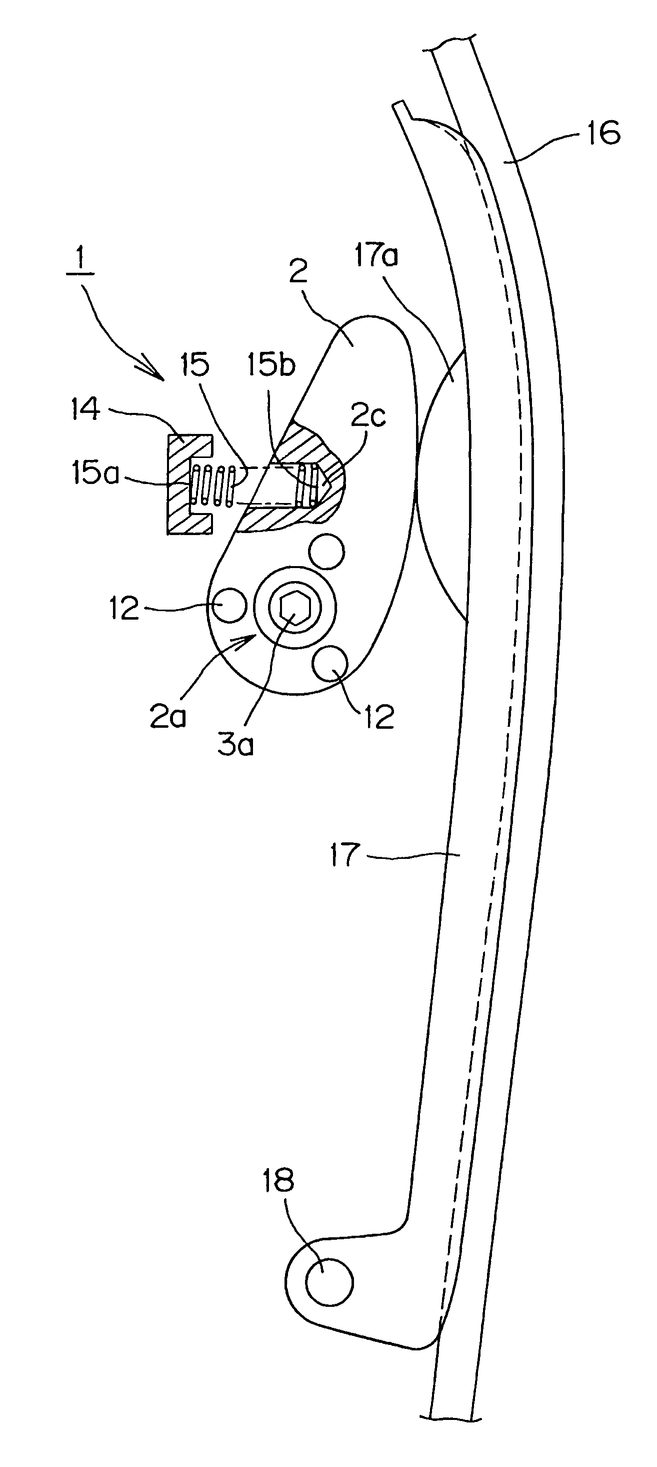
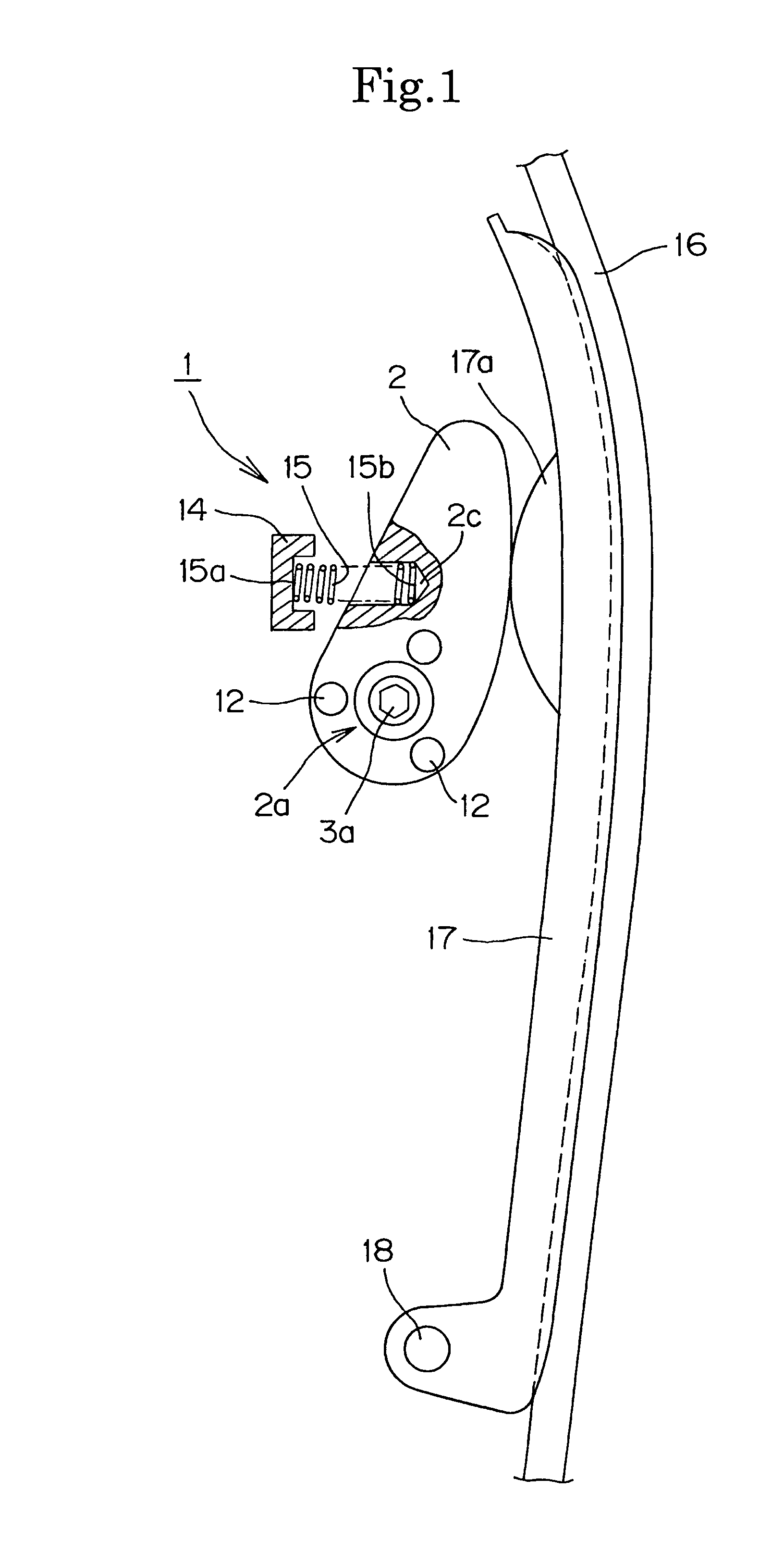
[0046]The tensioner is composed of a lever 22 having a one-way clutch 27 attached to its proximal portion 22a. The lever 22 is pivotally mounted on a base 24 by means of a shaft 23 and can be pivoted in a direction where tension is imparted to the chain or belt 16, but prevented by the one-way clutch 27 from pivoting in the opposite direction. The lever does not require an external biasing spring as in the case of the first embodiment, and accordingly can be hollow. However, if made hollow, it is preferably formed with an internal reinforcing rib 22f.

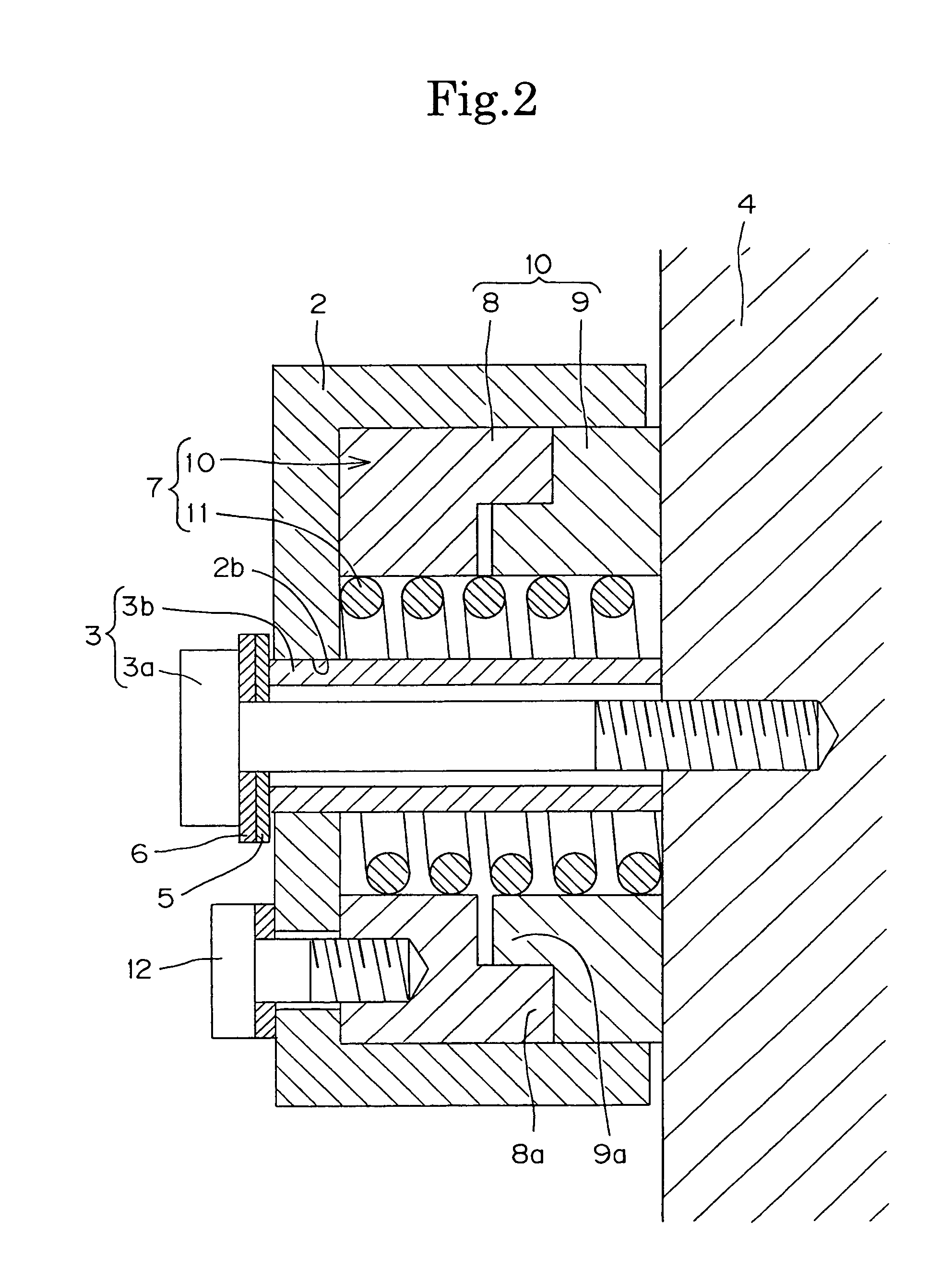
[0047]As shown in FIG. 5, the proximal portion of the lever 22 is mounted on a shaft 23 composed of a hex-head bolt 23a with a shaft 23b having a larger diameter than that of the shaft of bolt 3a. The shaft portion 23b of the shaft 23 extends, with a clearance, through a hole 22c in a boss 22b formed at the proximal portion 22a of the lever 22. The shaft 23 is attached to base 24 so that the lever 22 is pivotally mounted on the base 24...

second embodiment

[0054]In the operation of the tensioner of the second embodiment, a part of the lever 22 remote from the pivot axis presses against pad 17a of tensioner lever 17, urging the lever 17 so that it rotates about pin 18 and bears against the chain or belt 16, applying tension to the chain or belt.

[0055]As the chain or belt 16 loosens due to elongation over time, the lever 22 is gradually pivoted by the biasing force of the torsion coil spring 35 in a direction to increase the tension in the chain or belt 16. Pivoting of the lever 22 in the opposite direction is blocked by expansion of spring 31 against the inner circumferential surfaces of annular member 28 and 29. As a result, the tensioner lever 17 will always impart appropriate tension to the chain or belt 16 without backlash.

[0056]Here, as in the case of the first embodiment, the number of the parts is relatively small. Moreover, the compression spring and holder are eliminated. The tensioner can also be made light in weight, and its...


PUM


Abstract

A tensioner for maintaining tension in a timing chain or belt comprises a pivotally mounted lever body biased in a direction to increase tension in the chain or belt, and having a built-in, one-way clutch permitting the lever to pivot the tension-increasing direction but blocking pivoting movement in the opposite direction.

Description

FIELD OF THE INVENTION[0001]This invention relates to tensioners, and particularly to tensioner which imparts tension to a power transmission chain or belt through a tensioner lever in sliding-contact with the slack side of the chain or belt. The invention relates more specifically to a tensioner having a one-way clutch, which prevents the tensioner lever from pivoting in a direction such that tension in the transmission medium is reduced.BACKGROUND OF THE INVENTION[0002]Endless flexible power transmission media, in the form of chains or belts, have been widely used in the timing drive systems of engines, and also as for power transmission in industrial machinery and the like. Tensioners are used to prevent vibration in these chains and belts, and, at the same time, to take up slack resulting from their elongation. The tensioner typically presses against a tensioner lever, which is in sliding contact with the chain or belt. One well-known type of tensioner, known as a ratchet-type t...

Claims


Application Information

Patent Timeline
Patent Type & Authority Patents(United States)
IPC IPC(8): F16H7/08F16D41/20
CPCF16H7/0848F16H2007/0806F16H2007/081F16H2007/0853F16H2007/0872F16H7/0838
Inventor HASHIMOTO, HIROSHIKATO, MASAKI
Owner TSUBAKIMOTO CHAIN CO
Why Eureka
Try Eureka