Door lock assembly of automatic vending machine

A technology for vending machines and door locks, which is used in building locks, instruments, handling coins or valuable banknotes, etc., and can solve the problems of forgetting to use auxiliary locks, increasing prices, and not using keys for users.

Inactive Publication Date: 2004-09-01
FUJI ELECTRIC CO LTD
View PDF1 Cites 4 Cited by
  • Summary
  • Abstract
  • Description
  • Claims
  • Application Information

AI Technical Summary

Problems solved by technology

[0011] However, as mentioned above, the double locking method of adding an auxiliary lock on the handle lock can improve the anti-theft performance, but in addition to the increase in price due to the need for two cylinder locks, due to the need for operation by double keys For locking and unlocking, the management and oper

Method used


Image

  • Door lock assembly of automatic vending machine
  • Door lock assembly of automatic vending machine
  • Door lock assembly of automatic vending machine

Examples


Example Embodiment

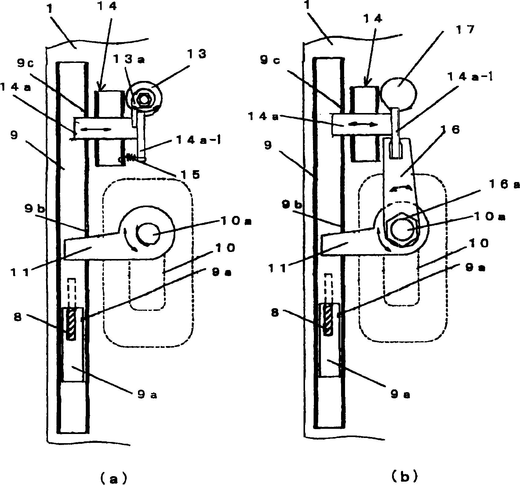
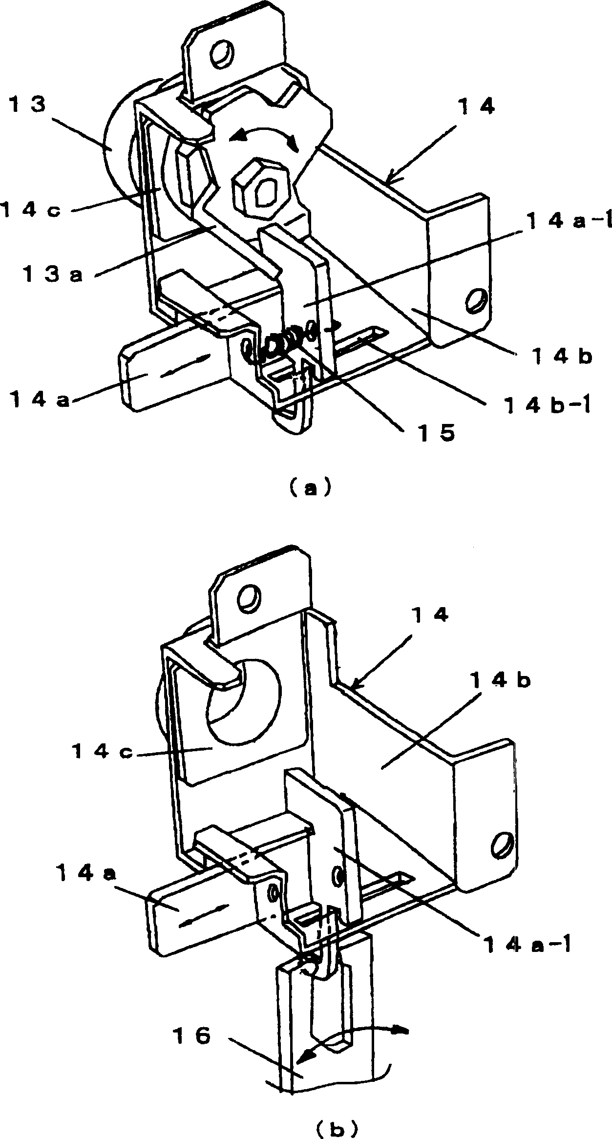
[0024] Below, according to Figure 1, figure 2 The examples shown illustrate embodiments of the invention. In addition, Figure 1 (a) and (b) are the door lock state diagrams corresponding to the two cases of the cylinder lock with the auxiliary lock as the optional component and the case without the auxiliary cylinder. figure 2 (a) and (b) show the detailed structure of the latch mechanism corresponding to Figure 1 (a) and (b), respectively. In the drawings of the embodiment, and Figure 4 , Figure 5 Corresponding parts are marked with the same symbols, so their description is omitted.

[0025] That is, on the door lock device of the illustrated embodiment, the Figure 4 , Figure 5 The said handle lock, which is the same as the current device, uses the auxiliary lock as an optional component to determine whether to install or not according to the user's requirements, and the latch mechanism 14 as a component of the auxiliary lock is fixed in advance as a permanent component indep...


PUM


Abstract

The invention provides a gate lock device of vending machine, using auxiliary lock as selected component, when the user does not need the auxiliary lock, not installing the auxiliary cylindrical lock, and instead, making the bolt mechanism on the gate as standing component coupled with the handle lock, thus able to realize double locking. In the gate lock device installed with lock base, lock rod sliding up and down, handle lock and auxiliary lock, it uses the bolt mechanism as standing component and installs the bolt mechanism on the gate in advance, in the state that the auxiliary lock is installed, makes the bolt coupled with the auxiliary cylindrical lock, and in the state that there is no auxiliary lock, by the auxiliary operating rod additionally combined on the handle lock, makes the bolt coupled with the handle lock, thus realizing double locking.

Description

technical field [0001] The invention relates to a door lock device arranged on an outer door in front of a vending machine cabinet. Background technique [0002] As we all know, the vending machine is equipped with a door lock device on the outer door, which is usually locked so that the door cannot be opened. [0003] image 3 It is the front view of the automatic vending machine. In the figure, 1 is the outer door arranged in front of the cabinet of the automatic vending machine; 2 is the display room where samples 3 of the vending products are displayed; 4 is the coin input port and the coin return handle. , banknote input port, display panel and other operation panels; 5 is a commodity take-out port; 6 is a handle lock with a lock. [0004] Next, use Figure 4 (a), (b) and Figure 5 (a), (b) The conventional structure and operation of the door lock device mounted on the automatic vending machine will be described. That is, by: a fork-shaped lock seat 8 protruding for...

Claims


Application Information

Patent Timeline
IPC IPC(8): E05B65/44G07F9/10
Inventor 田岛弘幸
Owner FUJI ELECTRIC CO LTD
Why Eureka
Try Eureka