
Filter arrangement for symmetrical and asymmetrical line systems

A filter and circuit technology, applied in the field of resonant band-pass filter devices, can solve the problems of expensive filters, less loss and select performance, etc., and achieve the effect of high packaging density

Inactive Publication Date: 2010-04-28
INFINEON TECH AG
View PDF4 Cites 0 Cited by
  • Summary
  • Abstract
  • Description
  • Claims
  • Application Information

AI Technical Summary

Problems solved by technology

[0015] With regard to the realization of bandpass filters known in the prior art, it can be concluded that the realization of these filters is too expensive and that they have too much loss in the passband and / or have only very little selectivity

Method used


Image

  • Filter arrangement for symmetrical and asymmetrical line systems
  • Filter arrangement for symmetrical and asymmetrical line systems
  • Filter arrangement for symmetrical and asymmetrical line systems

Examples


Embodiment Construction

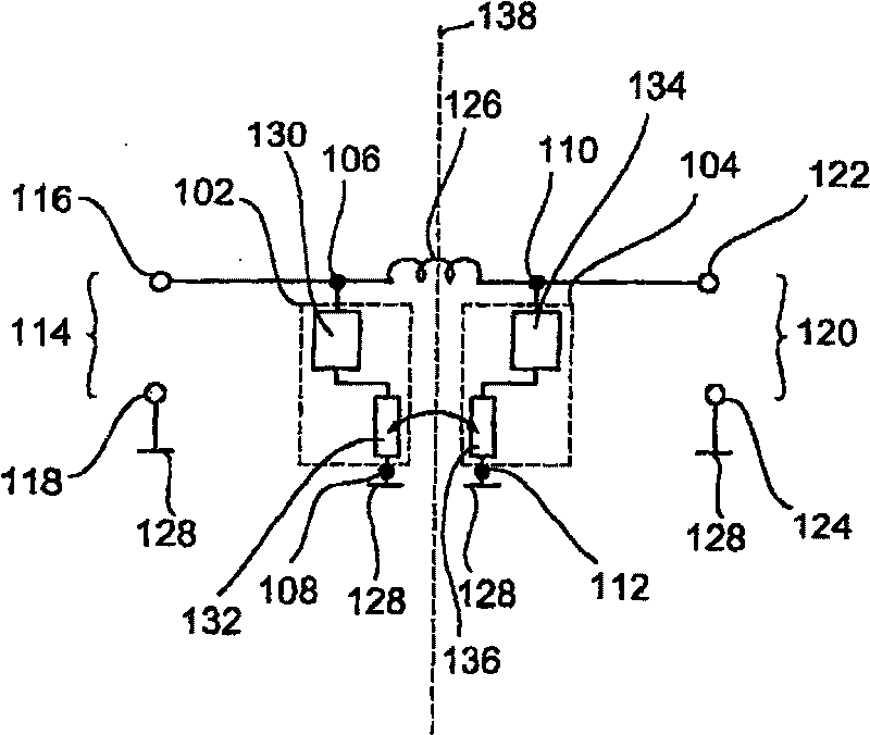
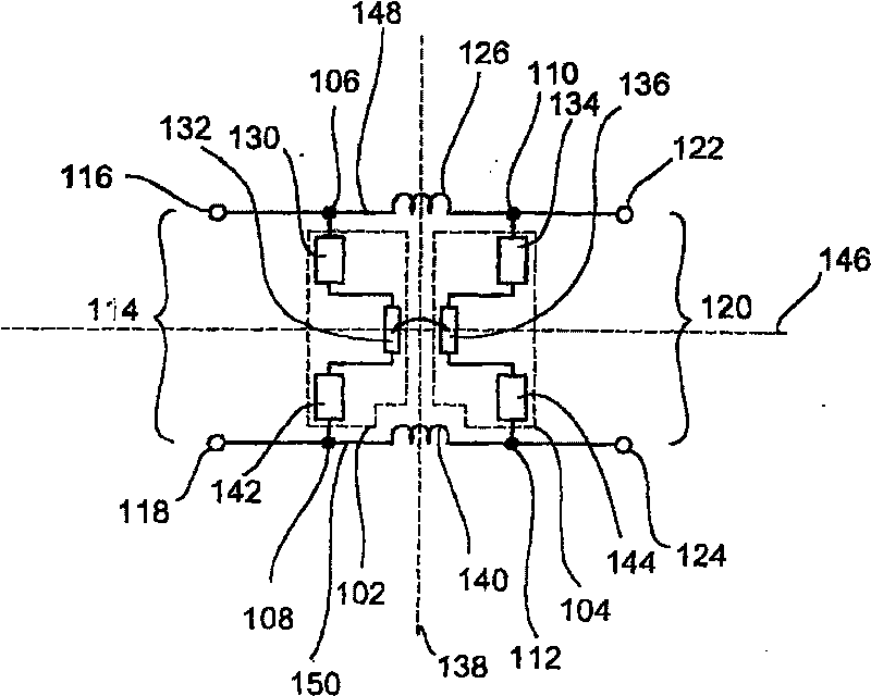
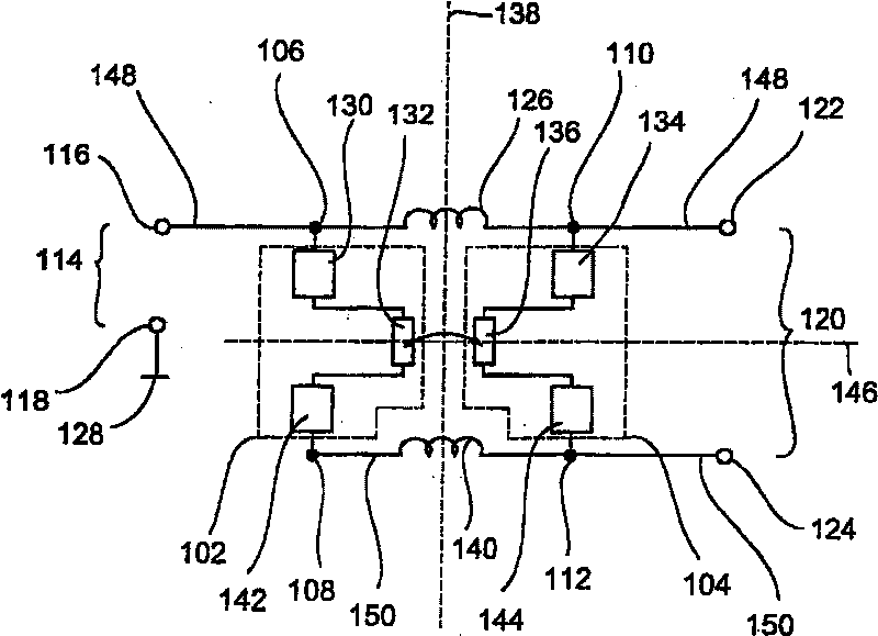
[0056] figure 1A resonant bandpass filter with an unbalanced input and output is presented as a first embodiment of the present invention. The resonant bandpass filter includes a first resonator device 102 and a second resonator device 104 . The first resonator device 102 is connected between a first node 106 and a second node 108 . The second resonator device 104 is connected between the third node 110 and the fourth node 112 . The resonant bandpass filter further includes an input port 114 , and the input port 114 includes a first input port node 116 and a second input port node 118 . In addition, an output port 120 is further provided, and the output port 120 includes a first output port node 122 and a second output port node 124 . Furthermore, the resonant bandpass filter also includes an inductance device 126 connected between the first node 106 and the third node 110 , such as an inductance device in the form of a coil.

[0057] exist figure 1 In the illustrated emb...


PUM


Abstract

A filter arrangement comprising a first resonator device (102) mounted between a first node (106) and a second node (108). A second resonator device (104) is mounted between a third node (110) and a fourth node (112). The first resonator device (102) and the second resonator device (104) are coupled to each other. An inductive component (126) is also mounted between the first node (106) and the third node (110).

Description

technical field [0001] This case relates to inventions related to filter devices, especially inventions related to resonator band-pass filter arrangements used in balanced and unbalanced line systems. Background technique [0002] Band-pass filters (band-pass filters) have become a necessary component for almost all microwave applications. Especially when the narrowband transmitting / receiving circuit (the so-called transceiver-circuit) is applied in the wireless mobile wireless communication system, it needs a band-pass filter so that all interfering signals are isolated from the used frequency band . Therefore, large interfering signals cannot limit the receiver, while small interfering signals do not worsen the basic noise. Furthermore, bandpass filters are also used in so-called multiband systems in order to select individual frequency bands via frequency separation filters, so-called diplexers. [0003] A good bandpass filter works by exhibiting as little electrical l...

Claims


Application Information

Patent Timeline
Patent Type & Authority Patents(China)
IPC IPC(8): H03H9/54H03H7/09H03H7/07H03H7/42H03H9/00
CPCH03H7/42H03H7/09H03H7/425H03H7/1708H03H9/0095H03H7/07H03H9/0028
Inventor H·霍耶尔曼恩J·鲁迪格尔
Owner INFINEON TECH AG
Learn More