

Keyboard structure
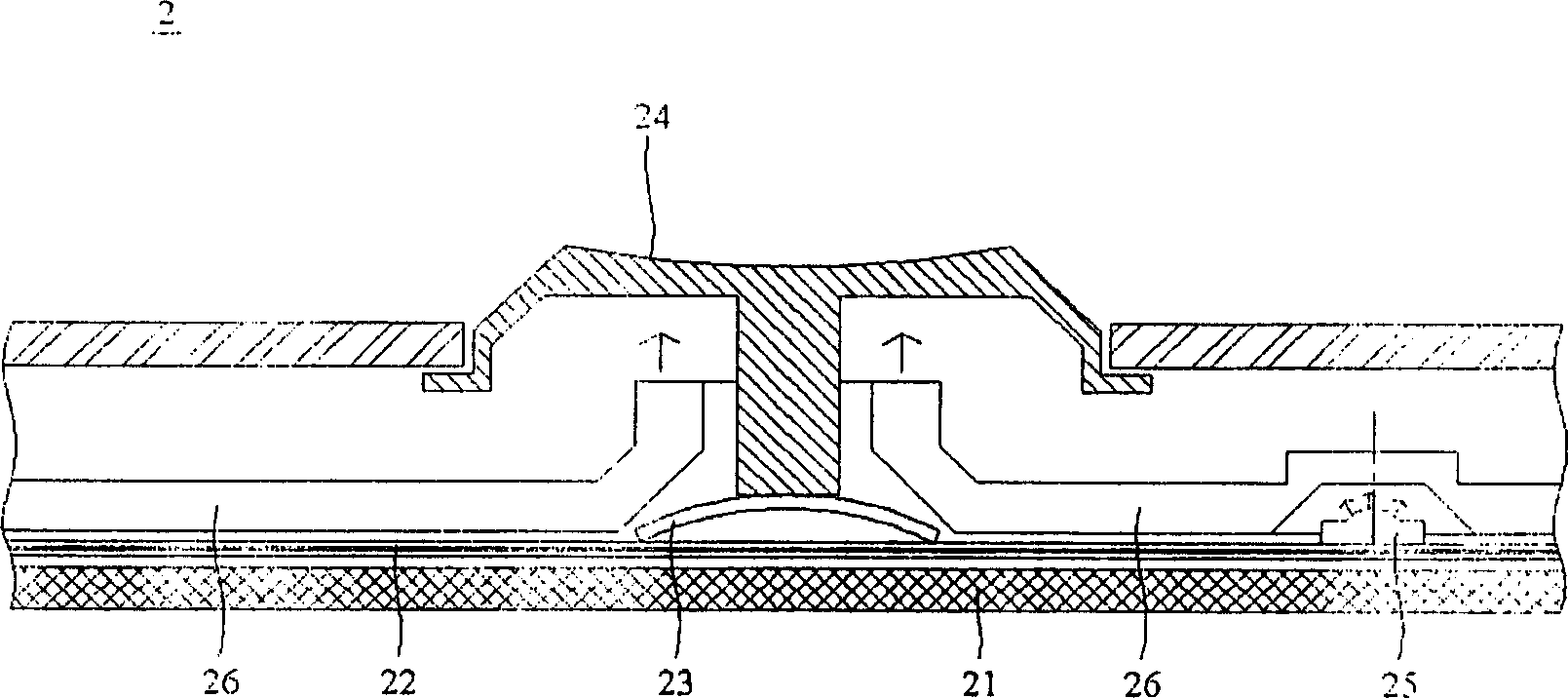
A keyboard and keycap technology, which is applied in the fields of instruments, electrical digital data processing, user/computer interaction input/output, etc., can solve the problems of keycap 24, such as discounted luminous effect, uneven luminescence, difficult manufacturing and forming, etc.
- Summary
- Abstract
- Description
- Claims
- Application Information
AI Technical Summary
Problems solved by technology
Method used
Image

Examples
no. 1 example
[0050] For ease of description, the present invention is described in detail with a computer keyboard structure having a scissors-like connection mechanism. Of course, the present invention is also applicable to keyboard structures of mobile phones and personal digital assistants (PDAs).
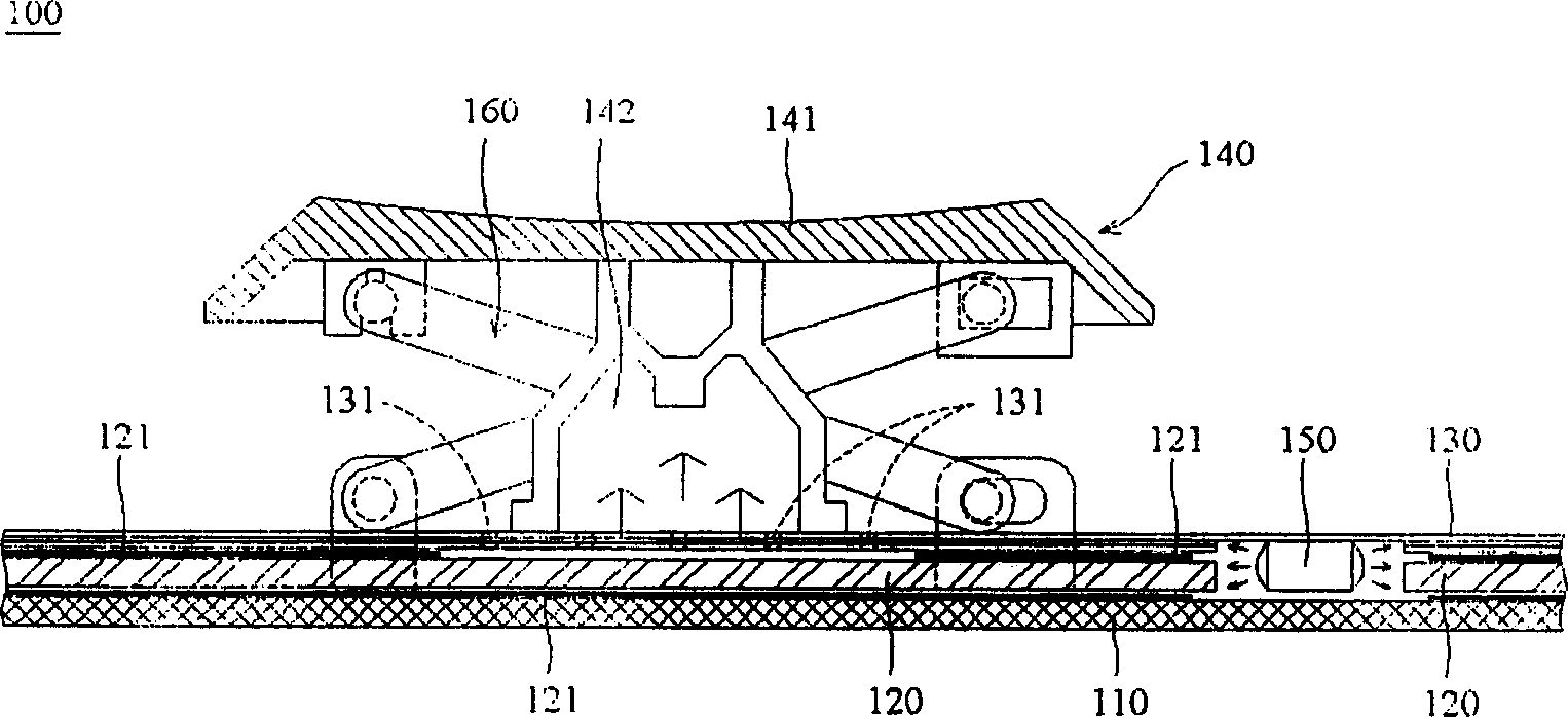
[0051] see figure 2 The keyboard structure 100 of this embodiment mainly includes a bottom plate 110 , a light guide 120 , a thin film circuit board 130 , a key assembly 140 and a light emitting component 150 . The light guide 120 is disposed on the bottom plate 110 . The thin film circuit board 130 is disposed on the light guide 120 . The button assembly 140 is disposed on the thin film circuit board 130 and has a key cap 141 and a transparent elastic body 142 . Meanwhile, the transparent elastic body 142 is located between the key cap 141 and the thin film circuit board 130 . The light-emitting component 150 is arranged on one side of the light guide 120 and is located under the thin fi...
no. 2 example
[0058] In this embodiment, components that are the same as those in the first embodiment are marked with the same symbols.
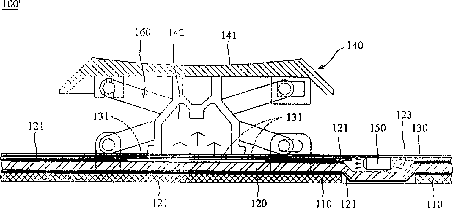
[0059] see image 3 , the keyboard structure 100' of this embodiment also includes a bottom plate 110, a light guide 120, a thin film circuit board 130, a key assembly 140 and a light emitting component 150. However, the light guide body 120 has a concave portion 123 , and the light emitting component 150 is disposed in the concave portion 123 .
[0060] Likewise, the light emitted by the light-emitting component 150 can be output or transmitted to the elastic body 142 and the keycap 141 through the conduction of the light guide body 120 and the reflection between the reflective layers 121 , so that the keycap 141 emits light evenly.
[0061] The configurations and functions of other components of this embodiment are the same as those of the first embodiment, so details will not be repeated here.
no. 3 example
[0063] In this embodiment, components that are the same as those in the first embodiment are marked with the same symbols.
[0064] see Figure 4The keyboard structure 100" of this embodiment also includes a bottom plate 110, a light guide 120, a thin film circuit board 130, a key assembly 140, and a light-emitting component 150. However, the light guide 120 has a concave portion 124, The light-emitting component 150 is disposed in the concave portion 124 . In addition, another circuit board 170 is disposed under the bottom plate 110 . The light-emitting component 150 is electrically connected to the circuit board 170 under the bottom plate 110 to obtain power.
[0065] The keyboard structure 100 ″ of this embodiment is very similar to the keyboard structure 100 ′ of the second embodiment. The concave portion 124 of the light guide 120 of the present embodiment faces the bottom plate 110 , while the light guide of the second embodiment The concave portion 123 of 120 faces the...
PUM
 Abstract
Description
Claims
Application Information