Paper feeding device and image forming apparatus

A technology of a paper feeding device and a paper feeding box, which is applied in the direction of the electric recording process using the charge pattern, the equipment and the object supply of the electric recording process using the charge pattern, and can solve the problem that the loading plate pushing on the opposite side of the measuring head cannot be changed. Problems such as volume and pressure, inability to make universal patterns for cartons, rising costs, etc.

Inactive Publication Date: 2004-10-06
RICOH KK
View PDF1 Cites 19 Cited by
  • Summary
  • Abstract
  • Description
  • Claims
  • Application Information

AI Technical Summary

Problems solved by technology

[0007] Most of the above-mentioned paper feeding cassettes are formed by resin into a box shape with an open top. However, due to factors such as the size and thickness of the media, there are very few of the same specifications for the loading plate or remaining amount detection mechanism installed inside, that is, the size of the loading plate, Pushing force etc. vary depending on factors such as media size or thickness
[0008] On the other hand, with respect to the residual amount detection mechanism, the probe etc. are directly actuated by the movement of the medium or the loading plate, and the structure of the above-mentioned probe parts varies with the structure of the paper feeding device, so sometimes the paper feeding cassette cannot be made universally. style
In particular, as shown in Patent Document 1, in the configuration in which the pressing mechanism for pressing the placing plate upward is arranged in the paper feeding cassette, since the pushing amount and pressure of the placing plate on the opposite side to the probe cannot be changed, Therefore, special parts are required
As a result, each image forming apparatus must prepare a dedicated sheet feeding cassette, leading to an increase in cost

Method used


Image

  • Paper feeding device and image forming apparatus
  • Paper feeding device and image forming apparatus
  • Paper feeding device and image forming apparatus

Examples


Embodiment Construction

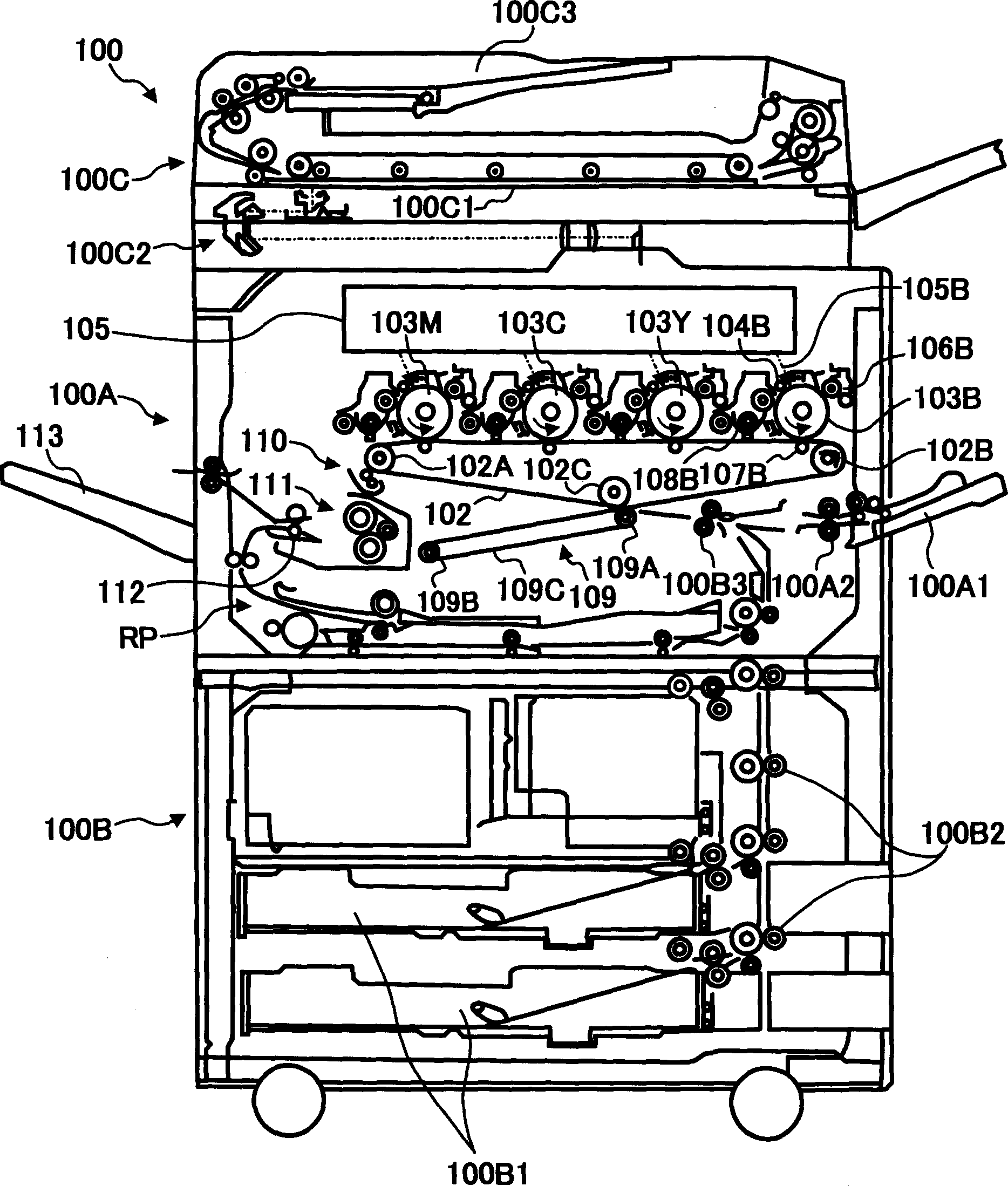
[0093] Hereinafter, preferred embodiments of the present invention will be described in detail with reference to the accompanying drawings.

[0094] figure 1 It schematically shows an example of an image forming device equipped with a paper feeding device according to an embodiment of the present invention. The image forming device shown in the figure adopts a tandem type, and is a color printer capable of forming multicolor images. Several photoreceptors are arranged in parallel as latent image carriers on which an image of the color corresponding to the color decomposition can be formed, and the toner images formed on each photoreceptor are superimposed and transferred on the intermediate transfer body, and then the superimposed image is transferred to the recording paper at once. Or transfer paper and other media. In the present invention, the image forming apparatus is not limited to figure 1 The illustrated printer is, needless to say, also applicable to image forming a...


PUM


Abstract

Provided is a paper feeding device provided with a configuration for suppressing increase of costs using a configuration of a main part as it is even when specifications differ for every image formation device. This feeding device provided with a feeding cassette for feeding a medium loaded on a loading plate 7 by a feeding means 10 is provided with a tray body part 2 in which the loading plate 7 is arranged and a guide unit part for conveying a medium attached to the tray body part 2. The guide unit part for conveying the medium is provided with a member 9 for raising the loading plate toward the feeding means 10 and an elevation driving member 24 connected with the member 9 to set an elevation form of the loading plate 7.

Description

technical field [0001] The present invention relates to a paper feeding device and an image forming apparatus, and more specifically, to a structure of a paper feeding cassette provided with a mounting plate on which recording media such as paper can be loaded. Background technique [0002] In an image forming apparatus such as a copying machine, a printer, a facsimile, or a printing machine, an image formed in an image forming processing section is transferred onto a recording medium such as recording paper, and a recorded output can be obtained. [0003] For example, take the case of a printer as an example, the photoreceptor is used as a latent image carrier, an electrostatic latent image is formed on the photoreceptor, the electrostatic latent image is developed by a developing device, and the visible image is processed, and output by a paper feeding device. A recording medium on which the above-mentioned visible image is transferred. Therefore, in the image forming app...

Claims


Application Information

Patent Timeline
Patent Type & Authority Applications(China)
IPC IPC(8): G03G15/00B65H1/00B65H1/04B65H1/12B65H1/26B65H3/68B65H7/04
CPCB65H2511/30B65H2553/612B65H1/266B65H2553/412B65H2511/212B65H7/04B65H1/04B65H2553/61B65H2220/01B65H2220/11B65H2220/03A43C9/04A43C9/00
Inventor 高桥俊明内田量之山田满頼本卫
Owner RICOH KK
Why Eureka
Try Eureka