X-Y objective talbe

A stage and slider technology, applied in positioning devices, feeding devices, large fixed members, etc., can solve the problems of difficult to obtain high speed, increased weight, and difficult to obtain high speed at the same time, to achieve high moving flatness, High stopping accuracy and cost reduction effects

Inactive Publication Date: 2004-10-06
SUMITOMO HEAVY IND LTD
View PDF1 Cites 12 Cited by
  • Summary
  • Abstract
  • Description
  • Claims
  • Application Information

AI Technical Summary

Problems solved by technology

[0012] Using a high-resolution linear scale, it is difficult to obtain high speed at the same time due to the limitation of its output signal frequency
In addition, with ball screws, it is difficult to achieve high speeds due to the constraints of dangerous speeds in the case of long strokes
[0013] On the other hand, in the case of not

Method used


Image

  • X-Y objective talbe
  • X-Y objective talbe
  • X-Y objective talbe

Examples


Example Embodiment

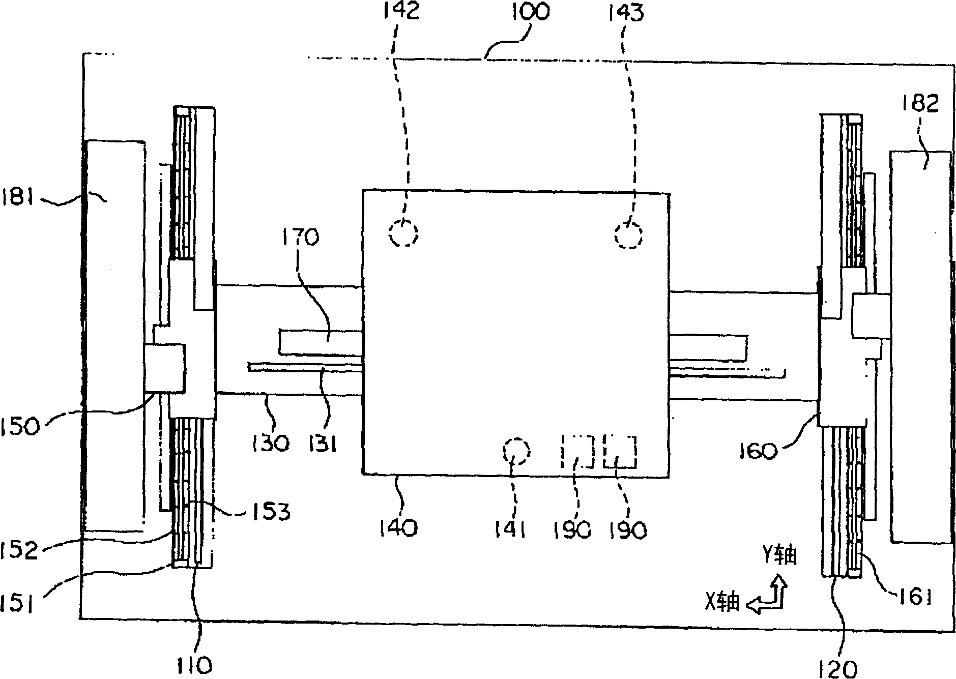
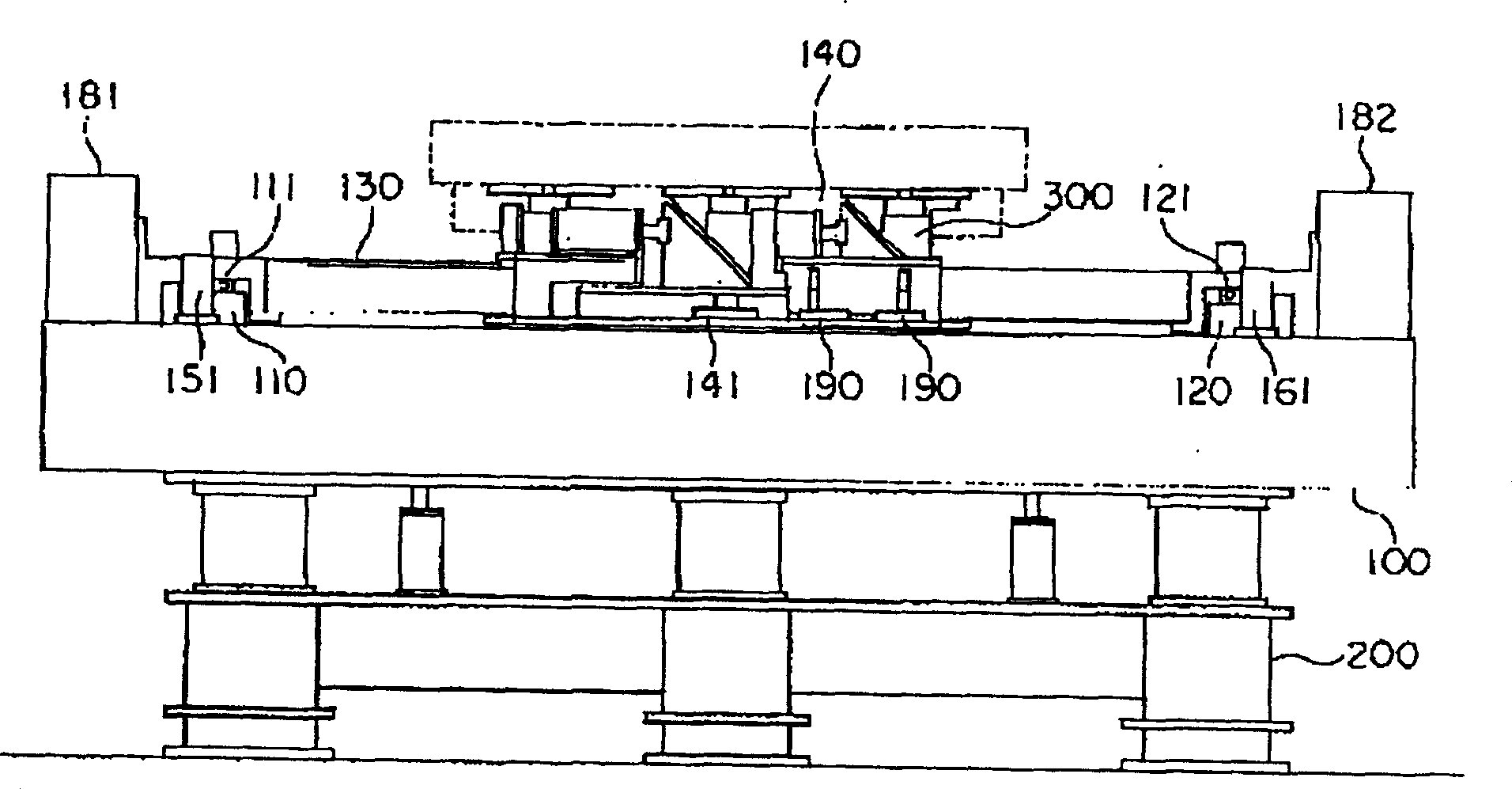
[0039] Below, refer tofigure 1 , figure 2 , to illustrate the preferred embodiment of the X-Y stage device according to the present invention.

[0040] exist figure 1 , figure 2 In the present X-Y stage device, the base 100 whose upper surface is surface-finished as a guide surface is fixed to the frame 200 . The base 100 is usually a stone slab. The fixing portion of the X-Y stage apparatus is the base 100 and guide rails 110 and 120 (first and second guide members) that are fixedly arranged on the base 100 at predetermined intervals. exist figure 1 , two directions of the X-axis and the Y-axis which are orthogonal to each other are shown. The guide rails 110 and 120 respectively extend in the Y-axis direction. In this X-Y stage device, the movable portion linearly guided in the Y-axis direction along the guide rails 11 and 120 is the Y slider 130 . The Y slider 130 is erected between the guide rails 110 and 120 , and the rolling bearings 111 and 121 are installed be...


PUM


Abstract

An x-y stage device is provided to obtain the high stop accuracy while reducing expensive components. Two guide rails(110,120) are fixed on a base(100). An Y slider(130) moves through the guide rails by combining with the guide rails. An X slider(140) is combined with the Y slider to move through the Y slider in perpendicularly. The Y slider is moved with separating from the surface of the base by supporting in the guide rails with rolling bearings. The X slider is moved by including the rolling bearing between the Y slider and moved with floating from the surface of the base by including plural static pressure bearings(141143). The stop accuracy is improved by a brake device(190).

Description

technical field [0001] The present invention relates to a stage device, and more particularly, to an X-Y stage device capable of moving a driven object such as a table in the X-axis direction and the Y-axis direction. Background technique [0002] As an example of the X-Y stage device, the X-Y stage device proposed by the present inventors will be described. Such an X-Y stage device is disclosed in Patent Document 1. [0003] 4 , the fixing part of the X-Y stage device is a base 20 whose upper surface is surface-finished as a guide surface, and guide rails 21 and 22 are fixedly arranged on the base 20 at predetermined intervals. In FIG. 4 , three directions of the X-axis, the Y-axis, and the Z-axis which are orthogonal to each other are shown. The guide rails 21 and 22 respectively have guide surfaces 21a and 22a extending in the Y-axis direction and facing each other. In the X-Y stage device, the movable parts that are linearly guided in the Y-axis direction along the gu...

Claims


Application Information

Patent Timeline
IPC IPC(8): B23Q1/28G12B5/00
CPCB23Q1/38B23Q1/62B23Q3/18B23Q5/28
Inventor 内海和晴小原达也
Owner SUMITOMO HEAVY IND LTD
Why Eureka
Try Eureka