Connector suitable for transmitting balance signal and substrate for mounting the connector

A connector and signal contact technology, applied in the field of the substrate on which the connector is installed, can solve problems such as high cost

Inactive Publication Date: 2004-10-20
JAPAN AVIATION ELECTRONICS IND LTD
View PDF2 Cites 1 Cited by
  • Summary
  • Abstract
  • Description
  • Claims
  • Application Information

AI Technical Summary

Problems solved by technology

The change of stamping shape requires high cost

Method used


Image

  • Connector suitable for transmitting balance signal and substrate for mounting the connector
  • Connector suitable for transmitting balance signal and substrate for mounting the connector
  • Connector suitable for transmitting balance signal and substrate for mounting the connector

Examples


Embodiment Construction

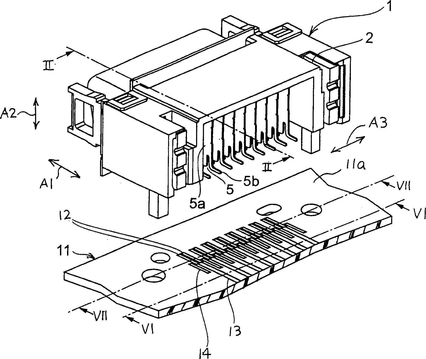
[0019] The following will refer to figure 1 and 2 describe a connector according to an embodiment of the present invention.

[0020] The connector shown by 1 in the figure is a so-called angled connector and is coupled and connected to a mating connector (not shown in the figure) in a first direction A1 in order to connect a transmission line for transmitting balanced signals. The connector 1 is mounted on a substrate 11 such as a printed circuit board in a second direction A2 perpendicular to the first direction A1. A direction perpendicular to the first and second directions A1 and A2 will be referred to as a third direction A3.

[0021] The connector 1 includes an insulator 2 and pairs of conductive signal contacts (signal contact pairs) 3 and 4 held by the insulator 2 . The signal contact pairs are arranged parallel to each other along the third direction A3 at a predetermined pitch. On opposite sides of each pair of signal contacts along the third direction A3, conduct...


PUM


Abstract

In a connector (1) including an insulator (2) and first and second signal contacts (3,4) held by the insulator, each of the first and the second signal contacts includes a fixed portion (3a,4a) fixed to the insulator, a contacting portion (3b,4b) connected to one end of the fixed portion and extending in a first direction (A1), a bent portion (3c,4c) connected to the other end of the fixed portion, a first intermediate portion (3d,4d) extending from the bent portion in the first direction, a second intermediate portion (3e,4e) extending from the first intermediate portion in a second direction (A2), and a terminal portion (3f,4f) extending from the second intermediate portion in the first direction. The first intermediate portions are placed at positions which are different from each other in the second direction. The second intermediate portions are different from each other in the first direction. The bent portions are shaped to make the first and the second signal contacts be substantially equal in total length to each other.

Description

[0001] This application claims priority from a prior Japanese application JP2003-111567, the disclosure of which is incorporated herein by reference. technical field [0002] The present invention relates to a connector suitable for connecting transmission lines or electric wires for transmitting balanced signals and a substrate for mounting the same. Background technique [0003] For example, a connector of this type is disclosed in Japanese Patent (JP-B) No. 3108239 and includes an insulator and a plurality of pairs of signal contacts (signal contact pairs) held by the insulator. Each of the pair of signal contacts is connected to a pair of transmission lines for transmitting balanced signals. [0004] Each of the signal contacts is initially formed by stamping. In this case, each signal contact tends to partially change in cross-sectional shape. Therefore, it is difficult to achieve impedance matching between the signal contacts in each of the signal contact pairs. [...

Claims


Application Information

Patent Timeline
Patent Type & Authority Applications(China)
IPC IPC(8): H01R13/6471H01R13/6474H01R13/6589H01R13/6595
CPCH01R23/005H01R23/6873H01R23/688H01R13/6471H01R13/6474H01R13/6589H01R13/6595
Inventor 进藤健
Owner JAPAN AVIATION ELECTRONICS IND LTD
Why Eureka
Try Eureka