Eureka AIR delivers breakthrough ideas for toughest innovation challenges, trusted by R&D personnel around the world.

Common mode noise filter

a filter and common mode technology, applied in the direction of coils, printed inductances, inductances, etc., can solve the problems of more significant common mode noise, increased noise, and increased noise, so as to improve impedance characteristics, and improve the effect of impedance characteristics

Inactive Publication Date: 2013-06-06
SAMSUNG ELECTRO MECHANICS CO LTD
View PDF2 Cites 16 Cited by
  • Summary
  • Abstract
  • Description
  • Claims
  • Application Information

AI Technical Summary

Benefits of technology

The present invention provides a thin film type common mode noise filter that solves problems of winding or laminated filters by improving impedance characteristics, having a high precision fine line width, and increasing permeability. This filter aims to be more effective and efficient in suppressing common mode noise.

Problems solved by technology

If the type of the noise is not confirmed, even though a noise suppression component is added to a circuit, the noise may further increase.
The common mode noise may be generated by impedance unbalance of a wiring system.
In addition, the higher a frequency is, the more significant the common mode noise occurs.
In addition, since the common mode noise is also transferred to the ground, or the like, to return while drawing a large loop, various noise disturbances may be generated even in a distant electronic device.

Method used


Image

  • Common mode noise filter
  • Common mode noise filter
  • Common mode noise filter

Examples


Embodiment Construction

[0024]Hereinafter, the present invention will be described in more detail with respect to the accompanying drawings.

[0025]Terms used in the present specification are for explaining the embodiments rather than limiting the present invention. Unless explicitly described to the contrary, a singular form includes a plural form in the present specification. The word “comprise” and variations such as “comprises” or “comprising,” will be understood to imply the inclusion of stated constituents, steps, operations and / or elements but not the exclusion of any other constituents, steps, operations and / or elements.

[0026]The present invention relates to a thin-film type common mode noise filter, which has a fine line width, excellent connectivity between upper and lower patterns to easily form an internal circuit pattern, and excellent connectivity with an external electrode, thereby making it possible to have excellent electrical characteristics and reliability.

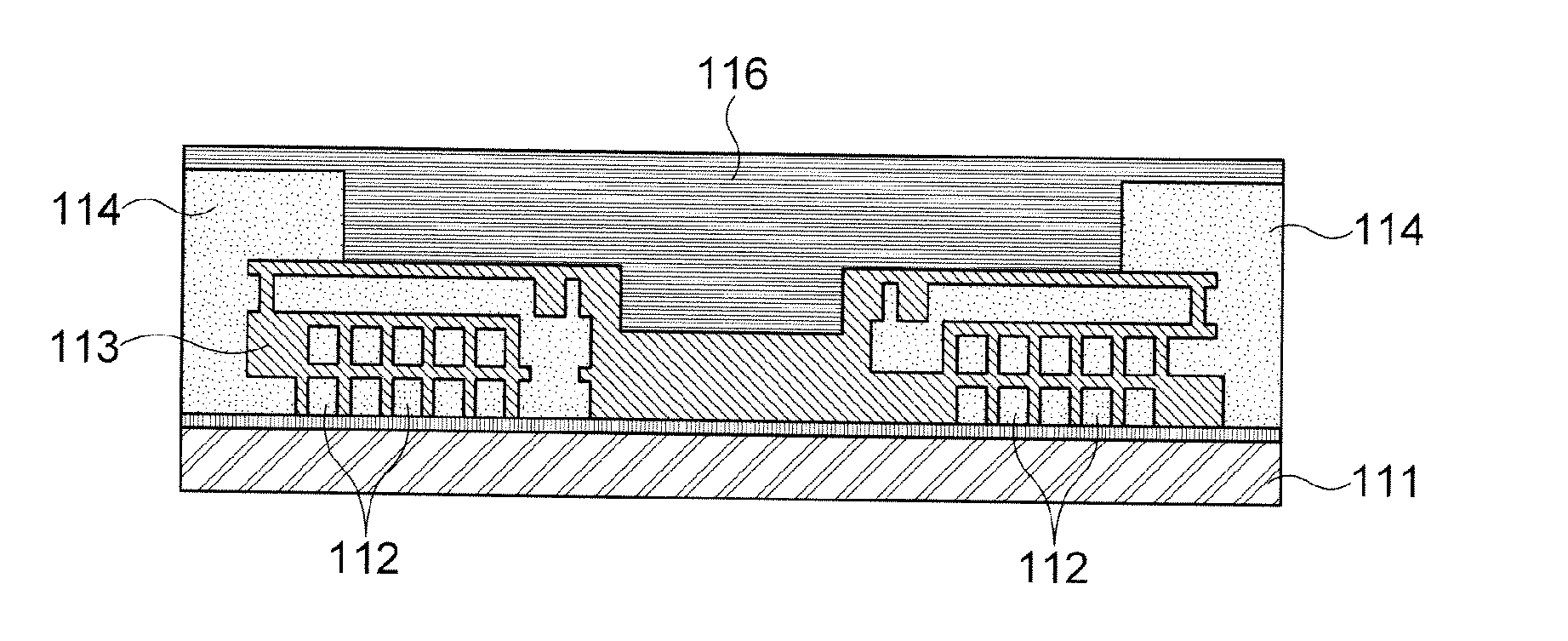
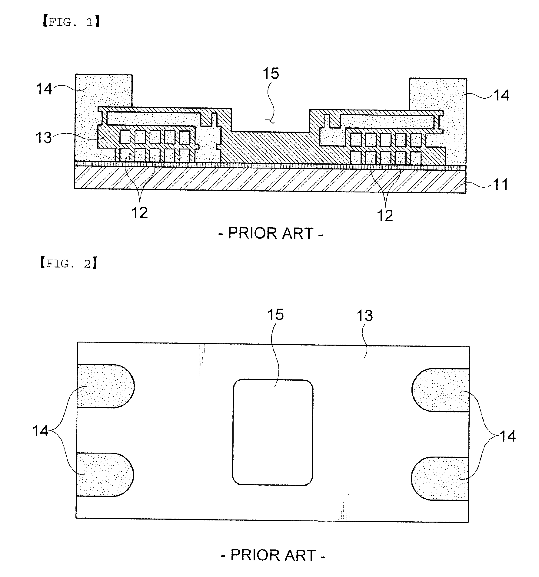
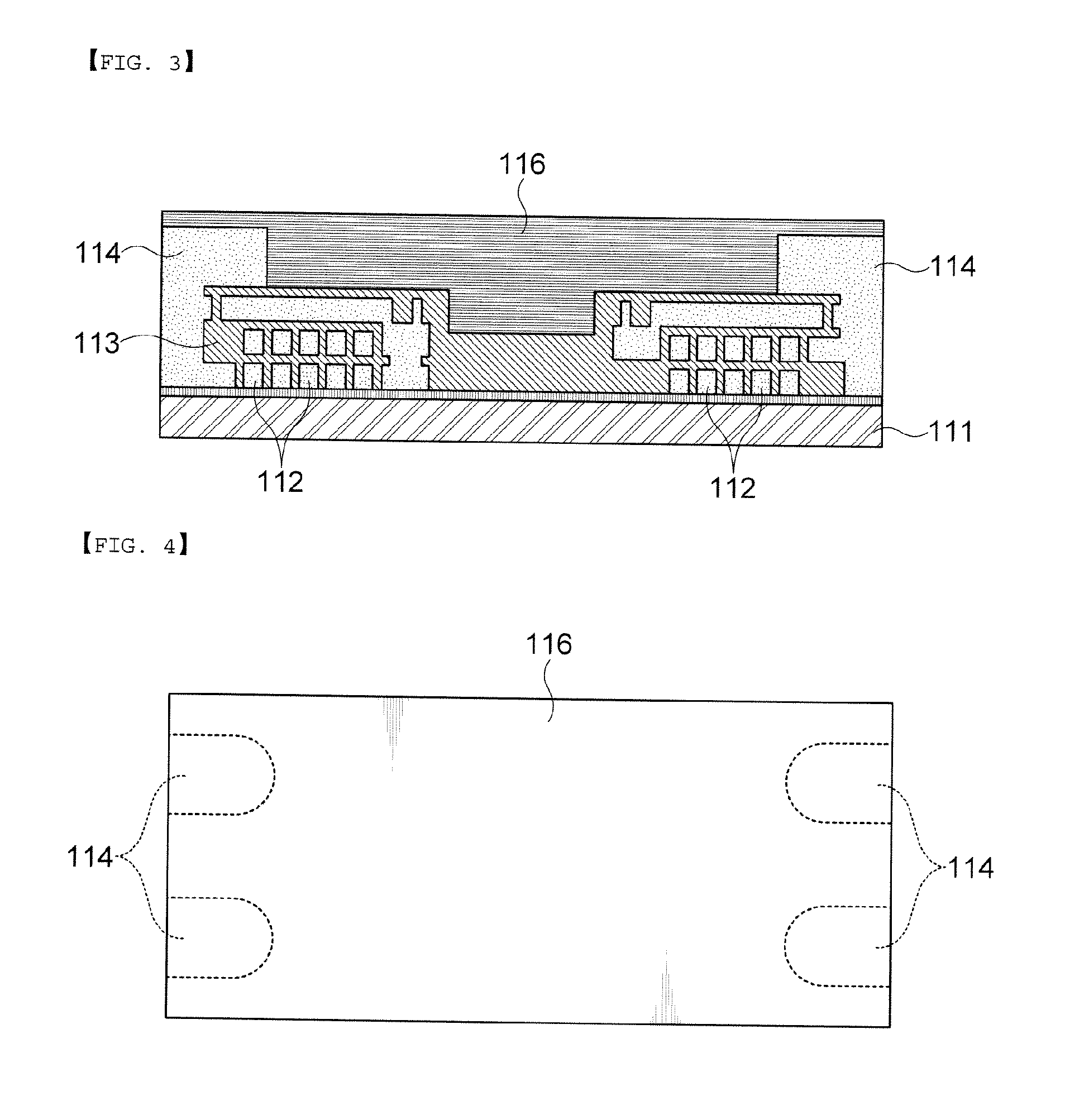
[0027]FIG. 3 shows a structure of...


PUM

PropertyMeasurementUnit
particle sizeaaaaaaaaaa
thicknessaaaaaaaaaa
conductiveaaaaaaaaaa

Abstract

Disclosed herein is a common mode noise filter including: a plurality of insulation layers configuring a laminated body formed on a substrate; internal electrode coils included in the plurality of insulation layers; external electrode terminals connected to an end portion of the internal electrode coils; and a magnetic layer formed on a surface of the laminated body. According to the present invention, the common mode noise filter has the magnetic layer including the conductive metal on the uppermost layer thereof, such that the permeability of the ferrite composite may be increased and the ferrite powder may be effectively compensated for the eddy current loss of the internal electrode coil, thereby making it possible to improve the impedance characteristics of the common mode noise filter.

Description

CROSS REFERENCE(S) TO RELATED APPLICATIONS[0001]This application claims the benefit under 35 U.S.C. Section 119 of Korean Patent Application Serial No. 10-2011-0129844, entitled “Common Mode Noise Filter” filed on Dec. 6, 2011, which is hereby incorporated by reference in its entirety into this application.BACKGROUND OF THE INVENTION[0002]1. Technical Field[0003]The present invention relates to a common mode noise filter.[0004]2. Description of the Related Art[0005]Electronic devices around us generate more or less radiation noise. Since noise freely and suddenly changes, noise immunity allowing an electronic device itself not to generate noise and preventing an electronic device from malfunctioning caused by external noise has been required. This is the basis of electromagnetic compatibility (EMC).[0006]Generally, conduction noise may be ‘bypassed’ to a ground by a condenser, or ‘be absorbed’ by a resistor and a ferrite core, a chip bead, or the like, to thereby be converted into h...

Claims


Application Information

Patent Timeline
Patent Type & Authority Applications(United States)
IPC IPC(8): H01F17/00
CPCH01F17/0006H01F2017/0093H01F2017/008H01F17/0013H01F17/00H01F27/29
Inventor LEE, SANG MOONWI, SUNG KWONKIM, YONG SUKYANG, JU HWANSIM, WON CHULKWAK, JEONG BOKCHO, JEONG MINYOO, YOUNG SEUCK
Owner SAMSUNG ELECTRO MECHANICS CO LTD
Why Eureka
Eureka Blog
Learn More