Method of manufacturing coil component

a manufacturing method and coil technology, applied in the field of coil components, can solve the problems of difficult compactness, low resistance value of coil conductor b>63/b> locally, and difficulty in manufacturing common mode choke coils with high impedance, and achieve excellent impedance characteristics

Active Publication Date: 2008-01-15
TDK CORPARATION
View PDF12 Cites 14 Cited by
  • Summary
  • Abstract
  • Description
  • Claims
  • Application Information

AI Technical Summary

Benefits of technology

[0017]An object of the invention is to provide a method of manufacturing a coil component which can manufacture a compact and low height coil component superior in impedance characteristics.
[0026]According to the invention, a compact and low height coil component excellent in impedance characteristics can be manufactured.

Problems solved by technology

However, a wound-wire coil provided by winding a copper wire or the like around a ferrite core has a problem in that it is difficult to make compact because of structural limitations.
Further, there is also a problem that the resistance value of the coil conductor 63 locally varies due to the unevenness of the sectional shape of the coil conductor 63.
Further, the manufacture of the common mode choke coil having high impedance becomes difficult by the unevenness of the film thickness of the insulating film 59c and the unevenness of the sectional shape of the coil conductor 63.

Method used


Image

  • Method of manufacturing coil component
  • Method of manufacturing coil component
  • Method of manufacturing coil component

Examples


Embodiment Construction

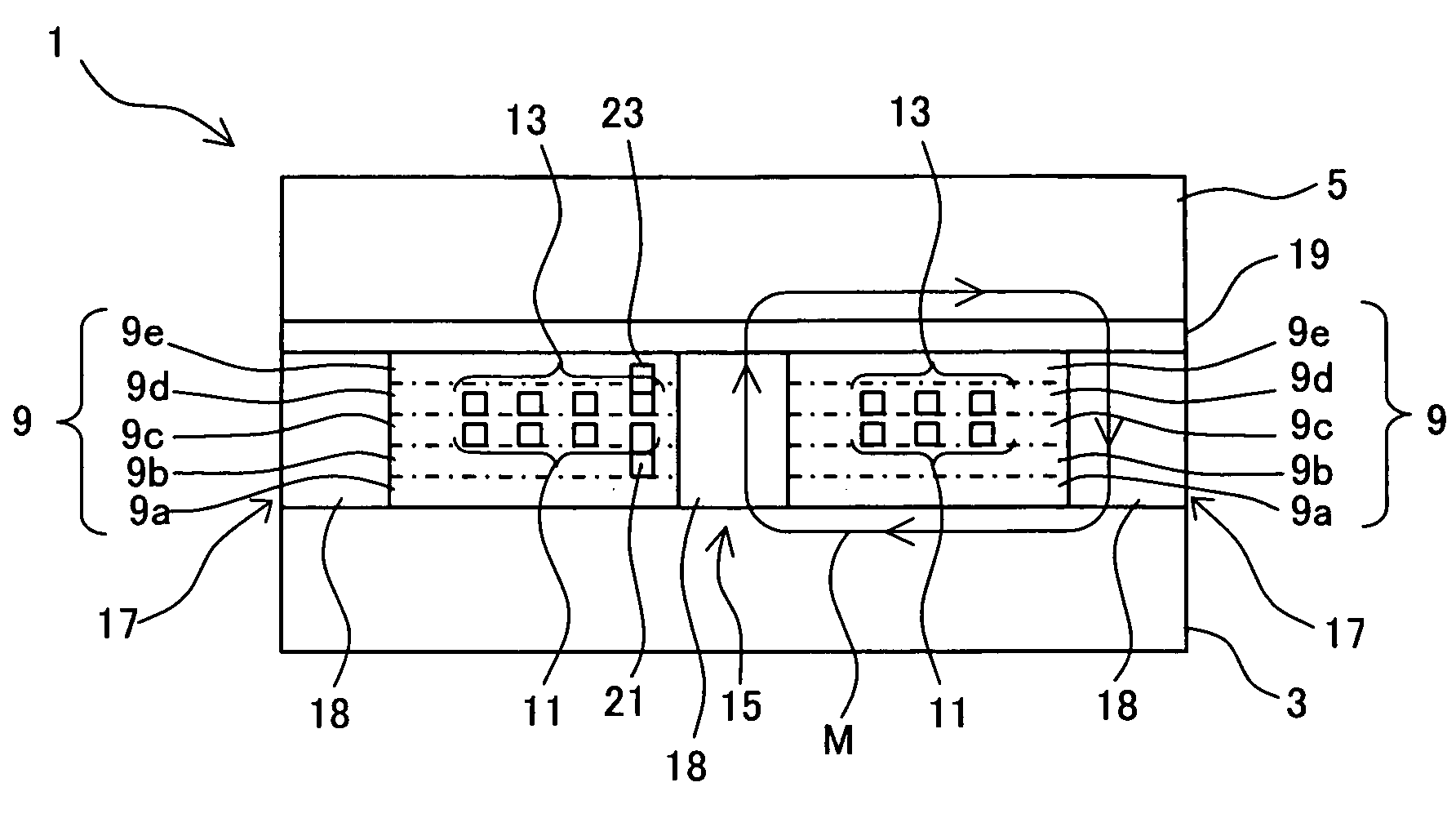
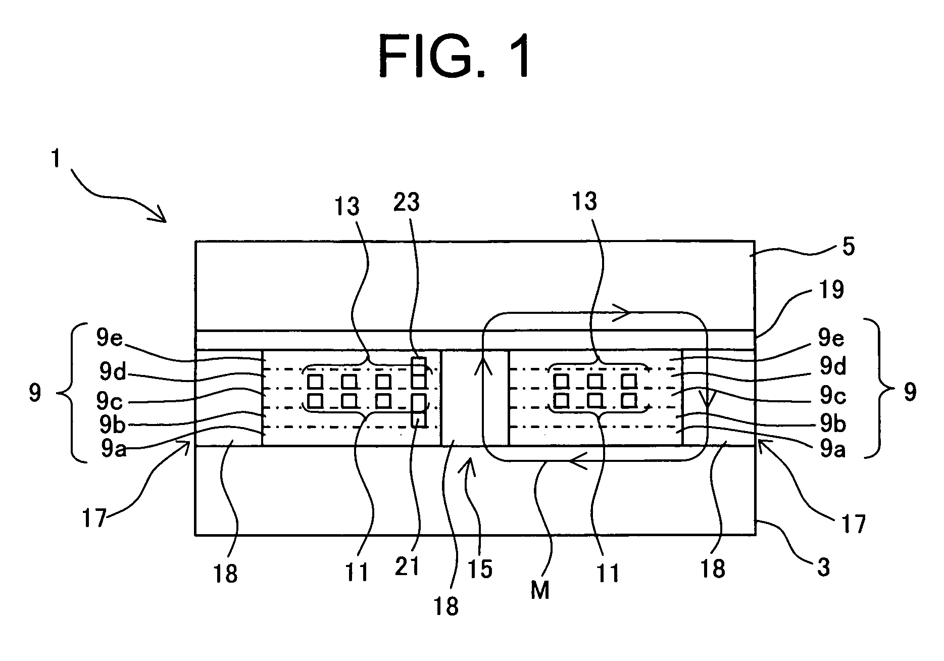
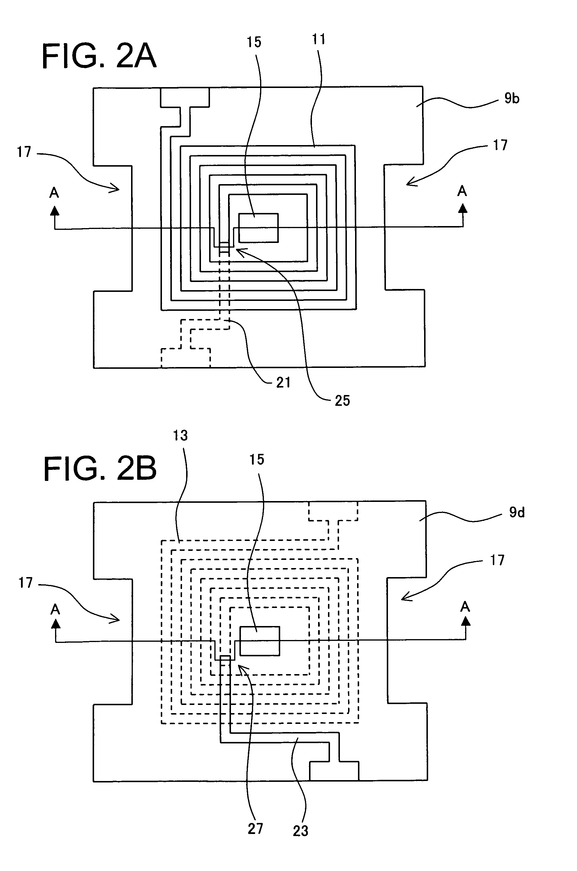
[0037]A coil component and a method of manufacturing the same according to an embodiment of the invention will be described with reference to FIGS. 1 to 7B. In this embodiment, a description will be made while a common mode choke coil for suppressing common mode current causing electromagnetic interference in a balanced transmission system is used as an example of the coil component. First, a structure of a common mode choke coil 1 will be described with reference to FIGS. 1 to 2B. FIG. 1 shows a section of the common mode choke coil 1 taken along an imaginary line A-A of FIGS. 2A and 2B. FIG. 2A shows a plane shape of the common mode choke coil 1 including a coil conductor 11. FIG. 2B shows a plane shape including a coil conductor 13.

[0038]As shown in FIG. 1, the common mode choke coil 1 of this embodiment has such a structure that an insulating film 9a, a lead terminal portion 21, an insulating film 9b, a coil conductor 11 made of conductive material, an insulating film 9c, a coil...


PUM

PropertyMeasurementUnit
thicknessaaaaaaaaaa
thicknessaaaaaaaaaa
conductiveaaaaaaaaaa

Abstract

The invention relates to a method of manufacturing a coil component uses as a major part of a common mode choke coil or a transformer, and there is provided a method of manufacturing a compact and low height coil component in which deterioration of impedance characteristics is low and reliability is high. An insulating film is formed on a magnetic substrate, and open regions are formed in the insulating film. A lead terminal portion is formed on the insulating film, and a planarizing film is formed on the open regions. An insulating film is formed and openings are formed in the insulating film at the open regions. A coil conductor is formed on the insulating film, and a planarizing film is further formed on the planarizing film. After a coil conductor is further formed on the coil conductor through the insulating film, the planarizing films are removed.

Description

BACKGROUND OF THE INVENTION[0001]1. Field of the Invention[0002]The present invention relates to a coil component uses as a major component or the like of a common mode choke coil or transformer and a method of manufacturing the same.[0003]2. Description of the Related Art[0004]Reductions in the size of electronic equipments such as personal computers and portable phones have resulted in demand for reductions in the size and thickness (low height) of electronic components such as coils and capacitors that are mounted on circuits in electronic equipments.[0005]However, a wound-wire coil provided by winding a copper wire or the like around a ferrite core has a problem in that it is difficult to make compact because of structural limitations. Under the circumstance, research and development is active on chip type coil components, which can be provided with a small size and a low height. Known chip type coil components include multi-layer type coil components provided by forming a coil ...

Claims


Application Information

Patent Timeline
Patent Type & Authority Patents(United States)
IPC IPC(8): H01F7/06H01F41/04G11B5/127
CPCG11B5/1274Y10T29/4906Y10T29/49073Y10T29/4902Y10T29/49071Y10T29/49064Y10T29/49069
Inventor YOSHIDA, MAKOTOOKUZAWA, NOBUYUKI
Owner TDK CORPARATION
Why Eureka
Try Eureka