Electrical connector

a technology of electrical connectors and connectors, applied in the direction of coupling device connections, coupling protective earth/shielding arrangements, securing/insulating coupling contact members, etc., can solve the problems of increasing the demand for higher signal transfer rates, increasing the number of signal lines, and requiring improvement in the resulting degradation of signal characteristics between signal lines. , to achieve the effect of reducing the size of the connector

Inactive Publication Date: 2009-12-10
FRAMATOME CONNECTORS INT SA
View PDF0 Cites 16 Cited by
  • Summary
  • Abstract
  • Description
  • Claims
  • Application Information

AI Technical Summary

Benefits of technology

[0007]In conventional differential transmission connectors, the structure is usually one in which a pair of signal lines and one or more drain lines inside a differential transmission cable are arranged in a single row on the same carrier as signal lines and ground lines. However, the spacing between the electrical lines must inevitably be reduced in order to accommodate increases in the required number of signal lines, thus causing degradation of the signal characteristics due to crosstalk between signal lines. In view of the above problems, the present invention has the purpose of providing a shield effect to improve the impedance characteristics of the signal lines by positioning a shell covering the connection points of each electrical line corresponding to the electrical contacts in the connector, connecting the drain lines to improve the impedance characteristics of the signal lines, and eliminating the ground electrical contacts corresponding to the drain lines which have conventionally been connected to the drain lines at both ends to reduce the connector width, make the dimensions of the connector more compact overall and improve its characteristics.
[0011]When, for example, using a dual-drain differential transmission cable, drain lines are usually positioned on both sides of the cable. Therefore, when two cables are positioned side by side, drain lines will be positioned on the outsides of the signal lines and ground line arranged as described above, and these can be connected to the metal shell in order to achieve a more compact structure.
[0013]When using a dual-drain differential transmission cable with two cables positioned side by side as described above, two drain lines will lie adjacent each other between a pair of signal lines from the cables, and when these are simultaneously connected to a single ground line contact, it is possible to arrange the lines so as to have a small spacing, thereby reducing the size of the connector overall.
[0015]When two dual-drain differential transmission cables having drain lines on both sides of a pair of signal lines are positioned side by side, the drain lines positioned outermost on the arrangement are connected to the shell, and the other adjacent pairs of drain lines are connected to a single ground line contact as ground lines. Due to this structure, while conventional configurations have ground line contacts for each of the drain lines positioned outermost, in the present invention, they are connected to the shell, so that it is possible to eliminate two of the contacts, thus contributing to an overall reduction in the size of the connectors.

Problems solved by technology

However, further increases in information capacity will raise the demand for higher signal transfer rates and increased numbers of signal lines for greater information transmission, and require improvements in the resulting degradation of signal characteristics between signal lines.

Method used


Image

  • Electrical connector
  • Electrical connector
  • Electrical connector

Examples


Embodiment Construction

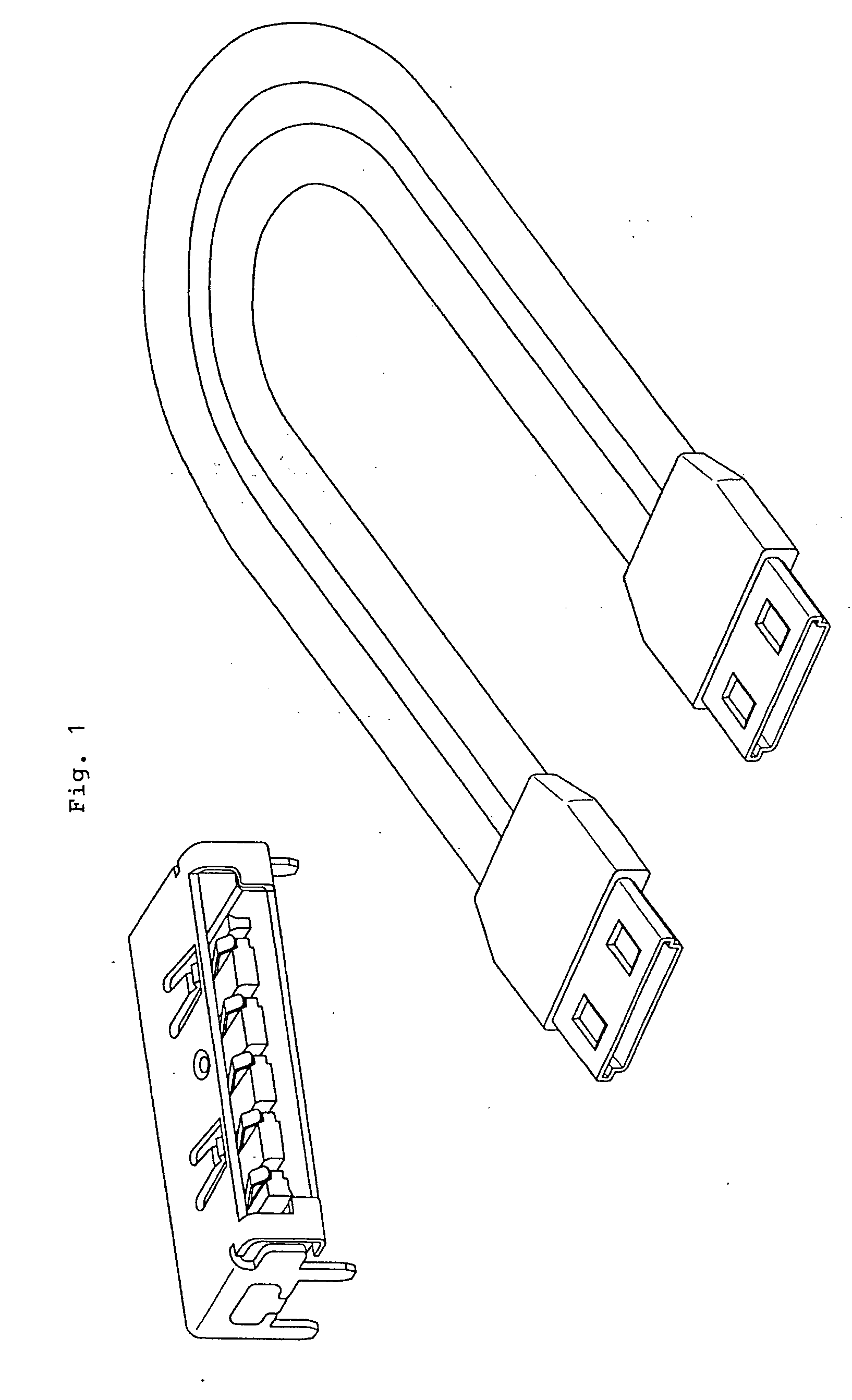
[0047]FIG. 1 is a perspective view of the external appearance of a board connector to be mounted on a circuit board, and a cable connector complementary to said board connector according to the present invention. The board connector is formed so as to be capable of accommodating the metal shell of the cable connector inside, and achieves an electrical connection when connected to a cable connector due to electrical contacts formed on the inside carrier coming into contact with corresponding electrical contacts.

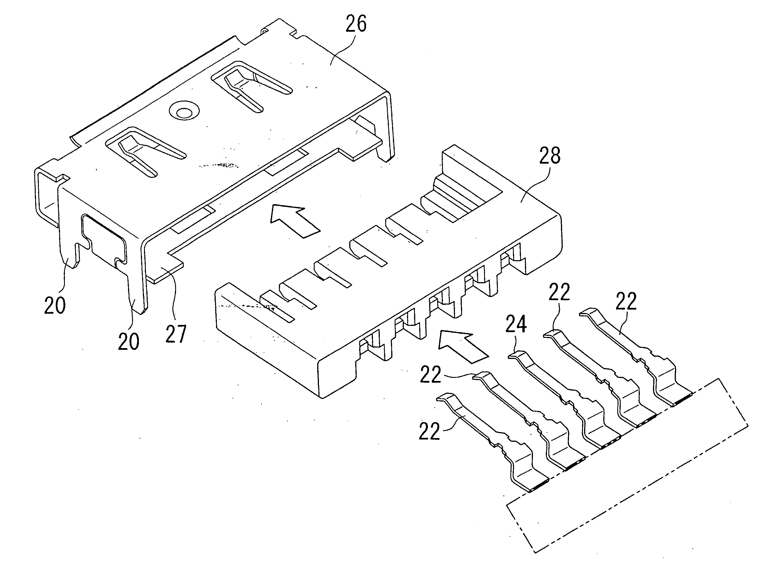
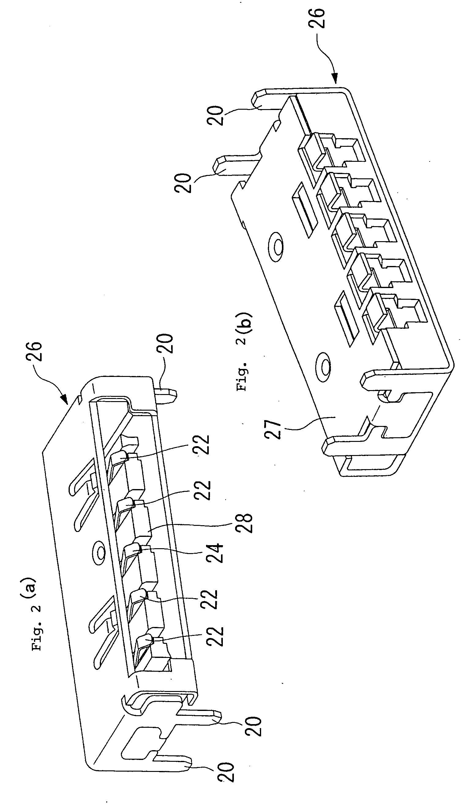
[0048]FIG. 2 shows a perspective view of the external appearance of a board connector according to the present invention. (a) is a top perspective view of a board connector according to the present invention. The casing 26 is open in the insertion direction of the cable connector, and is provided with four leg portions 20 for mounting on a circuit board that is not shown. Inside the casing 26, a carrier 28 is provided with two pairs of differential transmission signal line con...


PUM


Abstract

A differential transmission connector in which degradation of signal characteristics is improved. The connector being mated to a mating connector and making electrical connection of two or more differential transmission cables each having a pair of signal lines and at least one drain line, includes a contact for a pair of adjacent signal lines being connected with the pair of signal lines of the cable, a contact for the earth line being connected with the at least one drain line of the cable, a carrier having the contact for a pair of signal lines and the contact for the earth line arranged alternately in one row on an identical plane in the width direction intersecting the axial direction of the cable perpendicularly, and a shell covering the contact for signal lines, the contact for the earth line and the carrier, wherein a drain line located at least one end of the arrangement is connected with the shell.

Description

TECHNICAL FIELD[0001]The present invention pertains to a connector capable of electrically connecting a differential transmission cable, and further relates to a connector offering good high-speed signal characteristics due to its characteristic configuration.BACKGROUND ART[0002]With the increased information capacity and higher information transmission speeds of recent years, a data transfer specification known as serial ATA has become the standard interface between peripheral devices for personal computers and the like. Serial transmission refers to a format in which information is transmitted one bit at a time using a single transmission path. The smaller number of signal lines makes interference less likely to occur between signal lines, thus making serial transmission more advantageous for higher speeds. It is also advantageous in terms of the signal voltage, which can be set as low as about ±250 mV, and for being able to improve the resistance to noise from external sources by...

Claims


Application Information

Patent Timeline
Patent Type & Authority Applications(United States)
IPC IPC(8): H01R13/658H01R13/6471H01R13/6474H01R13/6592
CPCH01R9/034H01R13/41H01R13/65807H01R13/6581H01R2103/00H01R13/6471H01R24/562H01R13/65914
Inventor KAMEDA, YASUTOSHI
Owner FRAMATOME CONNECTORS INT SA
Why Eureka
Try Eureka