Rotor and electric generator

A generator and rotor technology, applied to wind power generation, synchronous motors with stationary armatures and rotating magnets, electromechanical devices, etc., can solve problems such as not being able to play or provide

Inactive Publication Date: 2004-10-20
格莱斯风能公司
View PDF1 Cites 13 Cited by
  • Summary
  • Abstract
  • Description
  • Claims
  • Application Information

AI Technical Summary

Problems solved by technology

[0015] While such a configuration has high peripheral speeds relative to a conventional equivalent direct drive design, the combined extremely large configuration would make some of the above problems worse and produce it in terms of the associated benefits of high peripheral speeds Some problems of its own, so it cannot play or provide some other benefits recognized by traditional direct drive designs (such as using two or three blades)
[0016] The bulky iron cores in traditionally designed direct drive generators can also be enough to make some problems worse, notably weight, efficiency losses, magnetic forces during assembly, and air gap forces

Method used


Image

  • Rotor and electric generator
  • Rotor and electric generator
  • Rotor and electric generator

Examples


Embodiment Construction

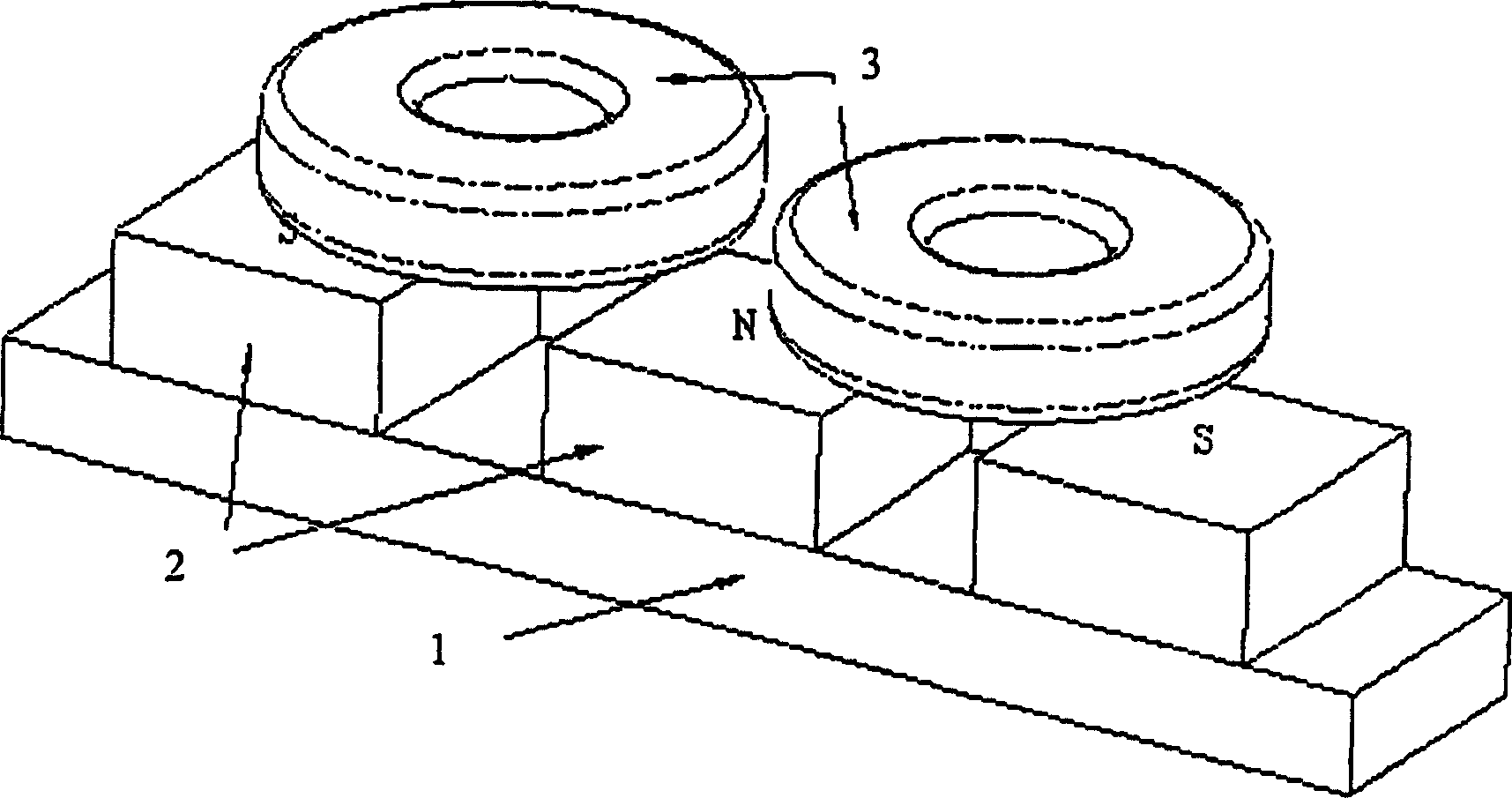
[0058] Various electromagnetic layout techniques may be employed and will be apparent to those skilled in the art. Below, the attached Figure 1 to Figure 3a and Figure 3b , with a specific embodiment, the present invention is described. Specifically, all examples use radially polarized magnets, an iron core that is not used on the stator, and both the rotor and stator use the structure of the present invention. However, it goes without saying that, in principle, the invention is equally applicable to other field geometries and / or iron-core or iron-less stator mechanisms, and that a rotor constructed according to the invention can be combined with any suitable stator, e.g. Used with a circumferentially extending stator on an arc.

[0059] figure 1 The best electromagnetic configuration is shown. In this embodiment, a ferromagnetic cylinder 1 fits a rotor back iron and has NdFeB permanent magnets 2 mounted on its outer surface. They can be fixed in any suitable way, such...


PUM


Abstract

A rotor for an electrical generator and a generator incorporating such a rotor, the rotor consisting of a central hub, a radially spaced concentric rim portion with rotor magnetic elements mounted upon it, and a plurality of elongate tension members extending generally between the hub and the rim, maintained substantially in tension so as to maintain the rim substantially in compression. The hub is rotatably driven by an axially spaced power drive means such as a wind or marine current turbine.

Description

technical field [0001] The present invention relates to a rotor of a generator and a generator equipped with the rotor, more specifically, to a rotor of a low-speed generator and a low-speed generator equipped with the rotor, that is to say, a power generator A machine in which a driving force is applied to a power mechanism, especially a rotating power mechanism, such as a turbomachine, and coupled to it, the rotor is turned by a direct drive or through a low-ratio transmission. Background technique [0002] The present invention relates in particular to large wind turbine generators and marine tidal current turbine generator installations and discusses the prior art and especially some embodiments of the invention presented previously. However, it will be believed that the invention has potential use in generators generally where the rotor is subjected to high torques. [0003] Initially, most industrial wind turbines used generators retrofitted with general-purpose induc...

Claims


Application Information

Patent Timeline
Patent Type & Authority Applications(China)
IPC IPC(8): H02K7/18H02K1/18H02K1/30H02K5/04H02K7/08H02K21/14
CPCH02K7/1838Y02E10/725H02K7/085H02K5/04H02K1/30H02K1/185H02K7/1823Y02E10/72
Inventor 保罗·戈登爱德华·斯普纳
Owner 格莱斯风能公司
Why Eureka
Try Eureka