Method for estimating elevation angle of intelligent antenna multi-subarray system

An antenna sub-array and smart antenna technology, which is applied in the field of angle-of-arrival estimation of smart antennas, can solve problems that do not involve multi-sub-array solutions, and achieve the effect of simple implementation and accurate estimation

Active Publication Date: 2009-12-30
ZTE CORP
View PDF4 Cites 13 Cited by
  • Summary
  • Abstract
  • Description
  • Claims
  • Application Information

AI Technical Summary

Problems solved by technology

The above-mentioned patent application does not involve the solution of related multiple sub-arrays

Method used


Image

  • Method for estimating elevation angle of intelligent antenna multi-subarray system
  • Method for estimating elevation angle of intelligent antenna multi-subarray system
  • Method for estimating elevation angle of intelligent antenna multi-subarray system

Examples


Embodiment Construction
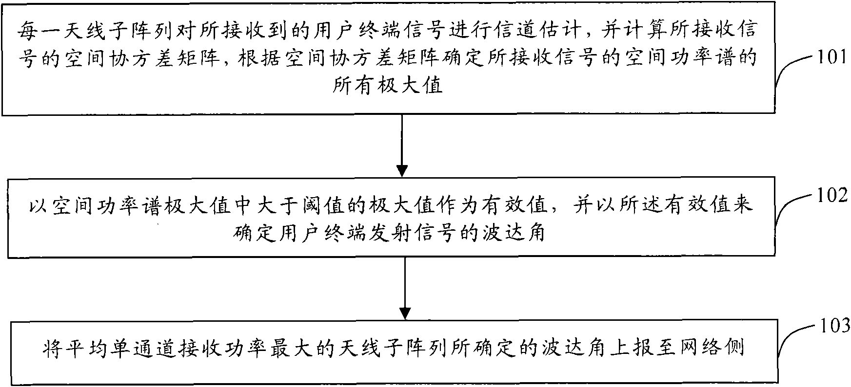
[0018] The basic idea of ​​the present invention is: the previous smart antenna system is a single-antenna sub-array, and there is no situation that most angle-of-arrival reporters need to choose to report. The present invention first performs channel estimation on the user terminal signals received by each antenna sub-array, and calculates the spatial covariance matrix of the received signals, and determines the maximum power value of the received signals according to the spatial covariance matrix, thereby determining some possible waves angle of arrival; finally calculate the average single-channel received power of each antenna subarray, and use the estimated angle of arrival of the largest antenna subarray as the reported value. The invention is simple to implement, and the estimated value of the reported angle of arrival is relatively accurate. The present invention will be described in detail below in conjunction with the accompanying drawings.

[0019] figure 1 It is ...


PUM


Abstract

The invention discloses a method for estimating an elevation angle of an intelligent antenna multi-subarray system, comprising the following steps: each antenna subarray estimates a channel of a received user terminal signal, computes a space covariance matrix of the received user terminal signal and then determines all maximal values of a space power spectrum of the received user terminal signal according to the space covariance matrix; taking one maximal value of the maximal values of the space power spectrum, which is greater than a threshold value, as an effective value, and determining the elevation angle of the signal sent by a user terminal by the effective value; and reporting the elevation angle determined by the antenna subarray with maximal average single-channel receiving power to a network side. The invention is easy to realize, and an elevation value of the reported elevation angle is more accurate.

Description

technical field [0001] The invention relates to a method for estimating the angle of arrival of a smart antenna, in particular to a method for estimating the angle of arrival of a smart antenna multi-subarray system. Background technique [0002] Smart antenna technology has become one of the most attractive technologies in mobile communications. Smart antennas are also called array antennas, which use space division multiple access technology to distinguish signals of the same frequency or same slot and same code channel by using the difference in the transmission direction of the signal, so as to maximize the use of limited channel resources. Compared with the non-directional antenna, the antenna gain of the uplink and downlink is greatly improved, the transmission power level is reduced, the signal-to-noise ratio is improved, and the influence of channel transmission fading is effectively overcome. Using the spatial characteristics of signal transmission and digital sign...

Claims


Application Information

Patent Timeline
Patent Type & Authority Applications(China)
IPC IPC(8): H04B7/08G01S3/74
Inventor 秦洪峰
Owner ZTE CORP
Why Eureka
Try Eureka