Method and arrangement for detecting the actuation of an operator-controlled element

A technology for operating elements and operating functions, which is applied to measuring devices, devices that prevent/restrict/restore the movement of parts of the control mechanism, and the layout of the power device control mechanism to achieve reliable identification and transformation.

Inactive Publication Date: 2004-11-03
ROBERT BOSCH GMBH
View PDF0 Cites 1 Cited by
  • Summary
  • Abstract
  • Description
  • Claims
  • Application Information

AI Technical Summary

Problems solved by technology

The problem is that over time due to the deformation of the pedal's bearing play, especially the plastic parts of the pedal, as well as due to temperature deviations and wear, the characteristic curve of the sensor used to detect the degree of pedal actuation changes and the activation automatically jumps. The switching point of the pedal with combined function or emergency switch function is moved to another actuation degree of the pedal

Method used


Image

  • Method and arrangement for detecting the actuation of an operator-controlled element
  • Method and arrangement for detecting the actuation of an operator-controlled element

Examples


Embodiment Construction

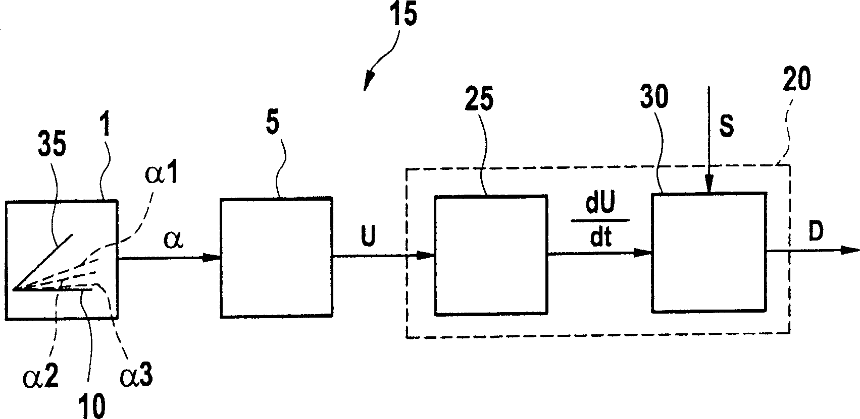
[0014] figure 1 15 shows the device according to the invention for detecting an operating function activated via the operating element 1 . The operating element 1 can be, for example, a pedal of a motor vehicle. Such a pedal 1 is usually actuated against a spring force, wherein several different degrees of actuation α can be set, depending on how strongly or with what force the driver actuates the pedal 1 . In this exemplary embodiment, however, various actuating functions of the pedal 1 are implemented depending on the degree of actuation α. The first operating function consists in setting a torque desired by the driver as a function of the degree of actuation α of the pedal 1 . The second operation function is an automatic jump function when the car has an automatic gear transmission, or an emergency switch function when the car has a speed limit function. The second actuating function is activated when the pedal 1 is actuated completely or at least as far as it abuts aga...


PUM


Abstract

A method and an arrangement (15) for detecting the actuation of an operator-controlled element (1) make possible a reliable detection of an operator-controlled function to be activated by the operator-controlled element (1) independently of environmental and wear conditions. The operator-controlled element (1) can be actuated with different adjustable degrees of actuation. Various operator-controlled functions of the operator-controlled element (1) are realized in dependence upon the degree of actuation. The operator-controlled element (1) is actuated against a spring force and at least two degrees of actuation are characterized by different spring constants. The at least one of the operator-controlled functions of the operator-controlled element (1) is detected in dependence upon the spring constant assigned to the instantaneous degree of actuation.

Description

technical field [0001] The invention relates to a method and a device for detecting the movement of an actuating element according to the preambles of the independent claims. Background technique [0002] It is well known that motor vehicles with automatic transmissions require an automatic jump function in order to signal a driver's desire for maximum acceleration to the engine control unit. In motor vehicles with a speed-limiting function, it is known to use an emergency switch, which switches off the speed-limiting function quickly in the event of a danger and thus allows maximum vehicle speed or vehicle acceleration to be achieved. Whether it is an automatic jump function or an emergency switch, it can be realized by pressing the driving pedal until a stop. For a driver pedal that is not mechanically connected to the throttle valve or to an adjusting element for regulating the fuel input, such as an injection valve, if a linear sensor or an angle sensor is arranged on t...

Claims


Application Information

Patent Timeline
Patent Type & Authority Applications(China)
IPC IPC(8): F02D11/10B60K26/02B60K28/00B60R16/02B60W50/08G01L1/00G05G1/30G05G5/03G06F19/00
CPCB60W50/0098
Inventor T·克洛茨比歇尔B·保尔H·卡茨米尔查克S·维斯
Owner ROBERT BOSCH GMBH
Why Eureka
Try Eureka