Rotation pair combination unit and motion decoupling parallel mechanism formed thereby
A technology of combining units and rotating pairs, applied in the directions of manipulators, program-controlled manipulators, manufacturing tools, etc., can solve the problems of restricting accuracy, not yet reported in literature, and cost reduction.
- Summary
- Abstract
- Description
- Claims
- Application Information
AI Technical Summary
Problems solved by technology
Method used
Image
Examples
Embodiment 1
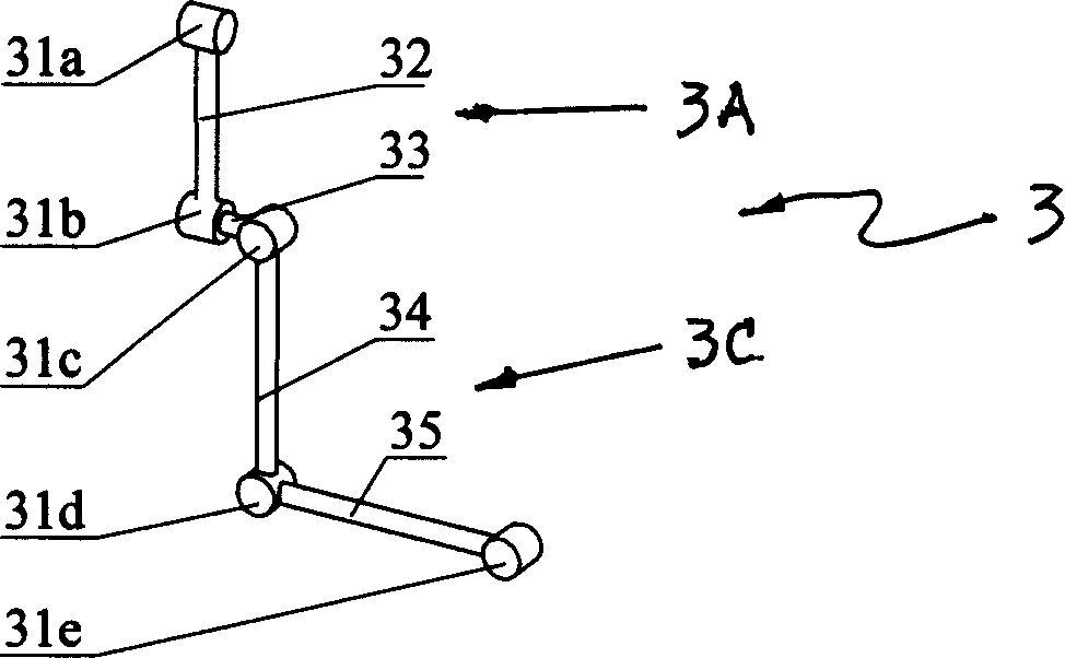
[0019] figure 1 A schematic diagram of an embodiment of a rotary pair combination unit (ie, the rotary pair combination unit 3 ) designed for the present invention. It includes two groups of rotating pairs: the first group of rotating pairs 3A includes 31a, 31b and the connecting rod 32 connecting the two rotating pairs; the second group of rotating pairs 3C includes 31c, 31d, 31e and the connecting rods connecting the three rotating pairs 34 and 35; two groups of rotating pairs 3A, 3C are vertically connected through the connecting rod 33 through the axes of said rotating pairs 31b, 31c to form a rotating pair combined unit 3 . Its design features are: the axes of the two groups of rotating pairs 3A, 3C are parallel to each other; the axes of the rotating pairs between the two groups are orthogonal to each other.
Embodiment 2
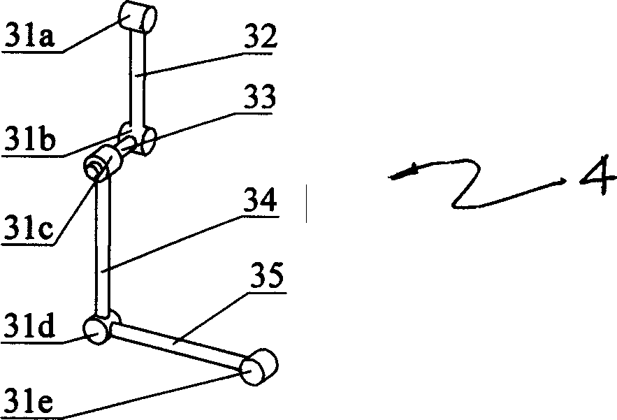
[0021] figure 2 A schematic diagram of an embodiment of another rotary pair combination unit (ie, the rotary pair combination unit 4 ) designed for the present invention. It also includes two groups of rotating pairs 3A, 3C: the first group of rotating pairs 3A also includes 31a, 31b and connecting rods 32 connecting the two rotating pairs; the second group of rotating pairs 3C also includes 31c, 31d, 31e and connecting rods The connecting rods 34, 35 of the revolving pair; the two groups of revolving pairs 3A, 3C are vertically connected through the connecting rod 33 through the revolving pairs 31b, 31c to form the revolving pair combination unit 4. Its design features are: the two groups of rotating pairs 3A, 3C, the axes of the rotating pairs in the same group are parallel to each other; the axes of the rotating pairs in different groups are orthogonal to each other.
[0022] The difference between Embodiment 2 and Embodiment 1, or between the swivel pair combination unit...
Embodiment 3
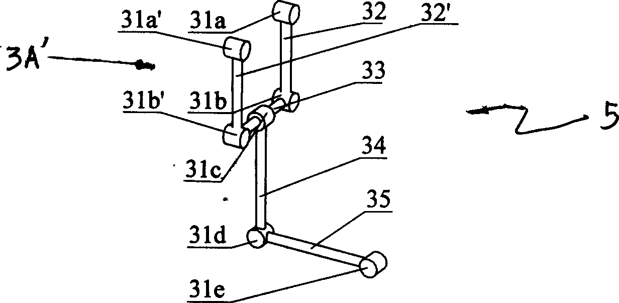
[0024] image 3 A schematic diagram of an embodiment of the third type of revolving pair assembly unit (ie, the revolving pair assembly unit 5 ) designed for the present invention. It is formed by adding a group of rotary sub-units 3A' with the same structure as the rotary sub-unit 3A on the basis of the rotary sub-combination unit 4. The added revolving pair unit 3A' is symmetrically connected with the connection point 31c as a symmetrical axis, that is to say, this group of revolving pair units (3A+3A') includes symmetrical revolving pairs 31a and 31a', and symmetrical revolving pairs 31b and 31b', and the symmetrical connecting rods 32 and 32', and the connecting rod 33 connecting the revolving pairs 31b and 31b'. Its design features are: the axes of the two groups of revolving pairs are parallel to each other; the axes of different groups of revolving pairs are orthogonal to each other.
[0025] Compared with Examples 1 and 2, Example 3 has a larger and more stable drivi...
PUM
 Abstract
Description
Claims
Application Information
 - R&D
- Intellectual Property
- Life Sciences
- Materials
- Tech Scout
- Unparalleled Data Quality
- Higher Quality Content
- 60% Fewer Hallucinations
Browse by: Latest US Patents, China's latest patents, Technical Efficacy Thesaurus, Application Domain, Technology Topic, Popular Technical Reports.
© 2025 PatSnap. All rights reserved.Legal|Privacy policy|Modern Slavery Act Transparency Statement|Sitemap|About US| Contact US: help@patsnap.com


