
Spinning stop valve

A globe valve and valve body technology, applied in sliding valves, valve details, valve devices, etc., can solve the problems of high power consumption, sealing leakage, and inability to remove debris on the sealing surface, and achieve low power consumption and reduce transmission torque. Effect

Inactive Publication Date: 2004-11-24
王洪生
View PDF0 Cites 5 Cited by
  • Summary
  • Abstract
  • Description
  • Claims
  • Application Information

AI Technical Summary

Problems solved by technology

[0002] At present, the sealing structure of various globe valves adopts extrusion type sealing. The valve body is filled with fluid medium, which makes the sealing structure easy to cause debris to remain. The dynamic sealing surface of the valve body moves to the static sealing surface in the form of extrusion, and the sealing surface cannot be removed. On the contrary, the sundries are squeezed and stored, resulting in leakage due to poor sealing. In addition, in order to make the sealing surface have sufficient pressure, the transmission device needs to provide a strong external force, resulting in large power consumption.

Method used


Image

  • Spinning stop valve
  • Spinning stop valve
  • Spinning stop valve

Examples


Embodiment Construction

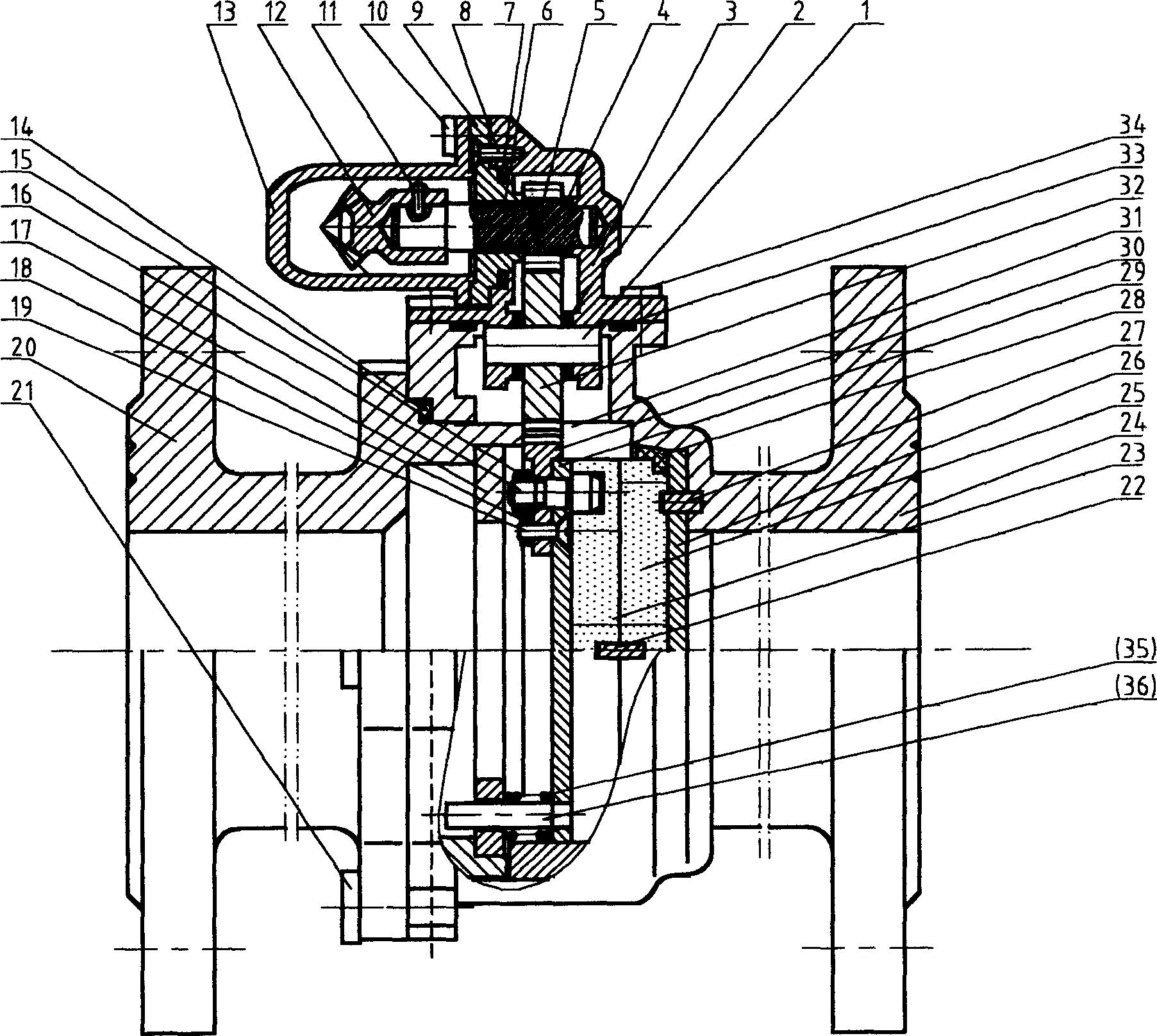
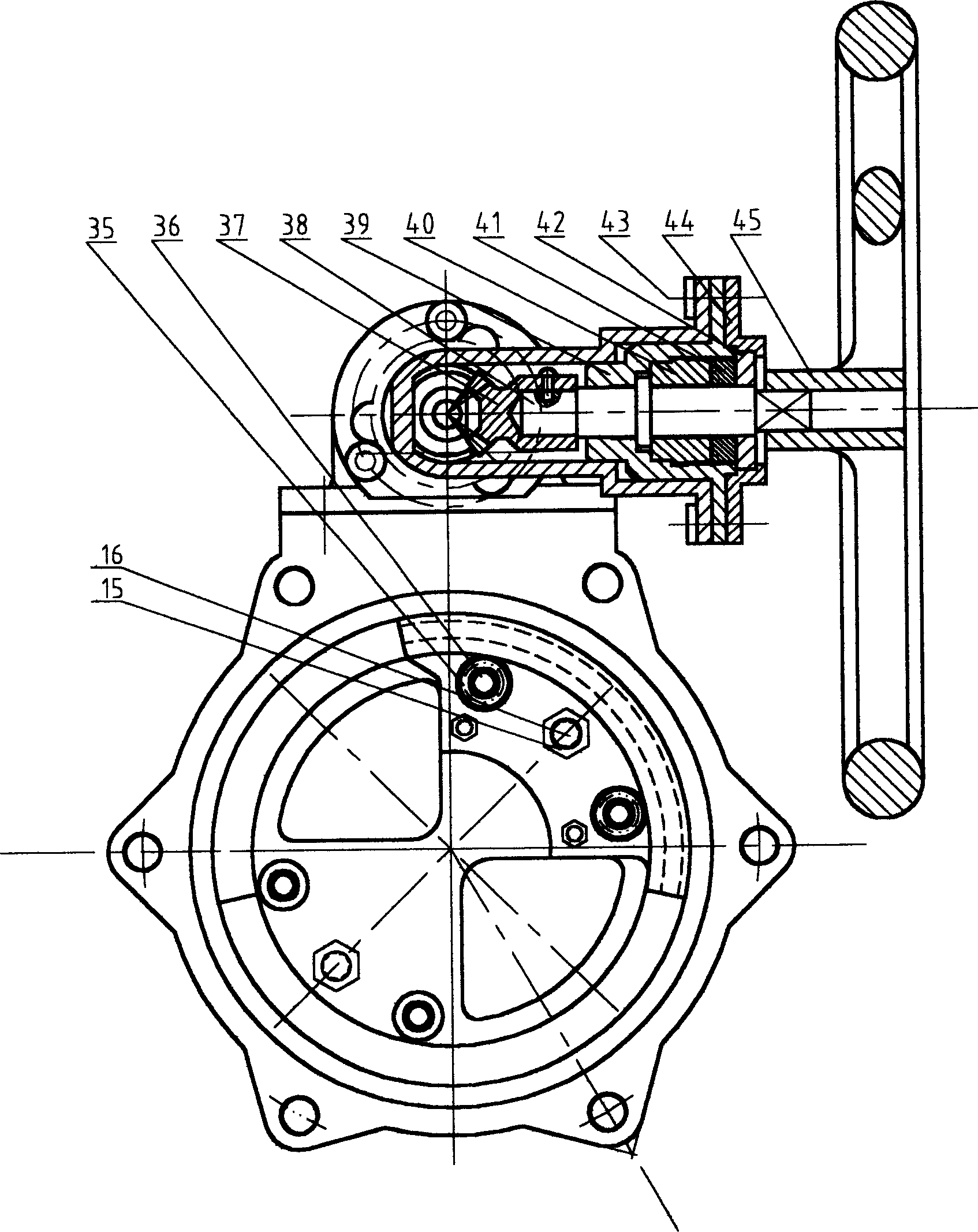
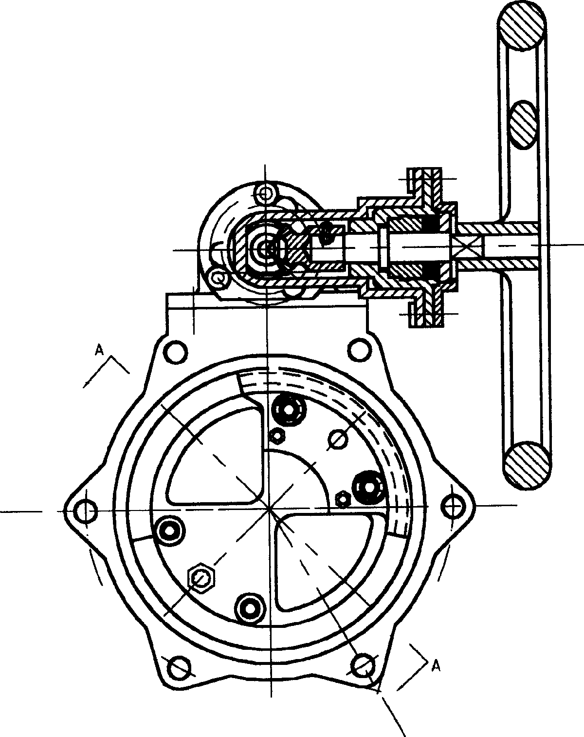
[0018] Refer to attached Figure 1-2 , the spinning type globe valve is composed of a transmission device on the side of the valve body, a pressure compensation device, and a spinning sealing device. The hand wheel 45 is connected to the front end of the transmission shaft 38, and the rear end is connected to the fixed bevel gear 37, which is crimped by the support sleeve 39 and the nut 40. The centering ring sleeve 42 is slidingly fitted, the support sleeve 39 is fixed on the support tube 13, the support tube 13 is fixed on the gear box 3 by the hexagonal bolt 10, and is fixed on the valve body 24 by the hexagonal bolt 34, and the front end of the driving gear shaft 5 is installed The bevel gear 12 meshes with the bevel gear 37. The middle part of the gear shaft 5 is covered with an O-ring 6 and the gear box cover 9 for rotation and sealing cooperation. The gear box cover 9 is fixed on the gear box 3 by the countersunk screw 8. The gear shaft The rear end of 5 is slidingly ma...


PUM


Abstract

The present invention discloses one kind of rotating pressure type cut-off valve technology, and aims at solving the technological problem of liquid leakage. The rotating pressure type cut-off valve consists of transmission shaft, bevel gears, driving gear shaft, driven gear shaft, segment gear, moving valve sheet and static valve sheet forming sealing, compression spring, protecting board, connecting board, valve body and other parts. The valve of the present invention is suitable for water, oil and other fluid medium with pressure of 0.01-3.7 MPa pressure and has good sealing performance.

Description

Technical field [0001] The invention belongs to a control device for a pipeline fluid medium, in particular to a shut-off spinning type stop valve for fluid in a pipeline. Background technique [0002] At present, the sealing structure of various globe valves adopts extrusion type sealing. The valve body is filled with fluid medium, which makes the sealing structure easy to cause debris to remain. The dynamic sealing surface of the valve body moves to the static sealing surface in the form of extrusion, and the sealing surface cannot be removed. On the contrary, the sundries are squeezed and stored, resulting in leakage due to poor sealing. In addition, in order to make the sealing surface have sufficient pressure, the transmission device needs to provide a strong external force, resulting in large power consumption. Contents of the invention [0003] The purpose of the present invention is to overcome the above technical deficiencies, and provide a spinning type globe val...

Claims


Application Information

Patent Timeline
IPC IPC(8): F16K3/08F16K31/53
Inventor 王洪生
Owner 王洪生
Learn More