
Zoning ink box for printer

A printing machine and ink fountain technology, which is applied in the field of printing machine ink fountains, can solve the problems of thin elastic ink fountain blades, uneven ink supply, and high processing costs

Inactive Publication Date: 2004-12-15
潍坊华光精工设备有限公司
View PDF0 Cites 6 Cited by
  • Summary
  • Abstract
  • Description
  • Claims
  • Application Information

AI Technical Summary

Problems solved by technology

[0002] In the traditional printing machine ink fountain, there are left and right stoppers installed on the left and right sides of the ink fountain body. The tail ends of the left and right stoppers are provided with spring plates, and the front ends of the left and right stoppers are provided with arc grooves that cooperate with the ink fountain rollers. The left and right sides of the ink fountain body Both ends are provided with support shafts connected to the wallboard of the printing machine, and the position of the ink fountain on the printing machine is adjusted by its positioning pillars. An elastic ink fountain blade is installed above the ink fountain body, and a row of elastic ink fountain blades is installed on the top of the ink fountain body. The adjustment screw on the upper part controls the ink supply volume of the ink fountain by adjusting the screw. The disadvantage of the ink fountain of this structure is that due to the elasticity of the elastic ink fountain blade itself, local adjustment of the ink supply volume is likely to cause ink volume in adjacent areas. Changes, resulting in uneven ink supply, and a certain part of the elastic ink fountain blade is likely to be elastically deformed due to the top pressure of the adjustment screw, it is difficult to meet the ink supply requirements of high-end printed matter, and the overall elastic ink fountain blade is thin and flat. The requirements are high, the manufacturing accuracy is difficult to meet the use requirements, and the processing cost is high

Method used


Image

  • Zoning ink box for printer
  • Zoning ink box for printer

Examples


Embodiment Construction

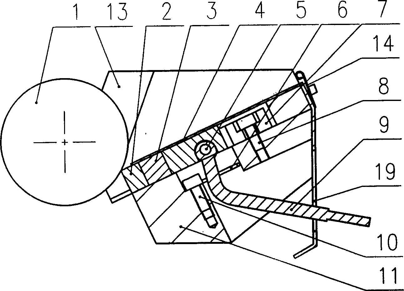
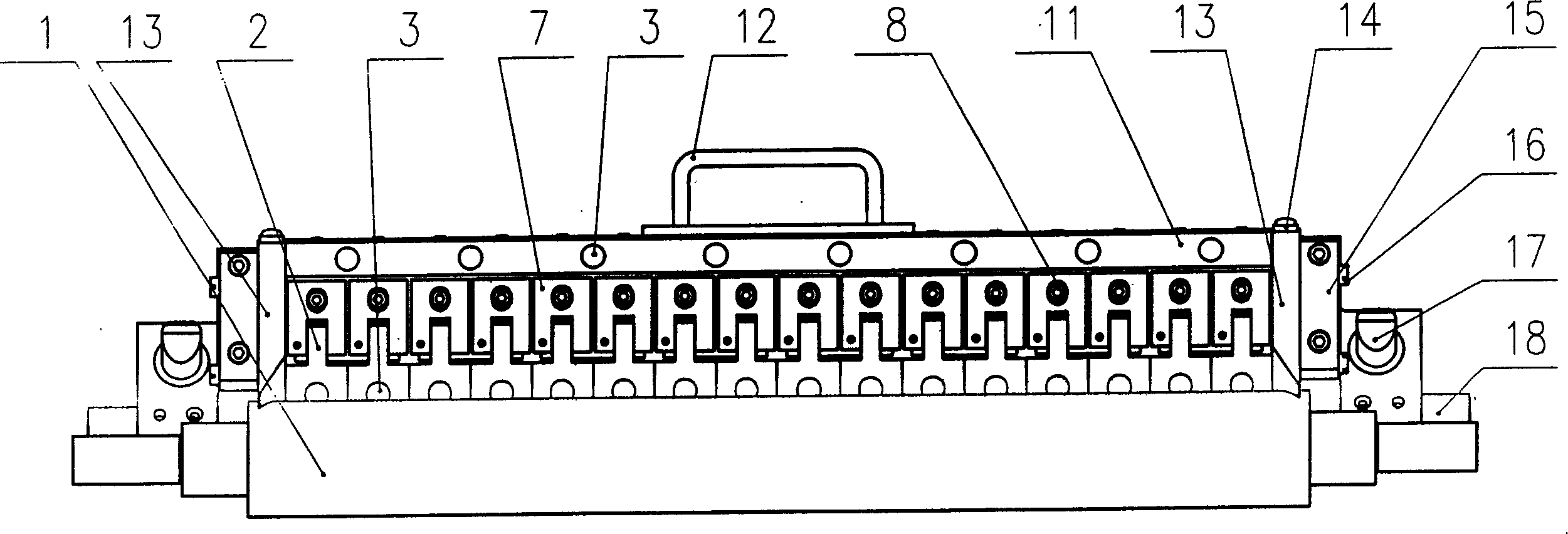
[0012] The partitioned ink fountain of the printing machine shown in the accompanying drawings includes an ink fountain body 11, and stoppers 13 are installed on both sides of the ink fountain body 11, and a spring leaf 14 is installed at the end of the stopper 13, so that the stopper is close to the ink fountain roller 1, and the stopper The front end of the block 13 is provided with an arc groove matching with the ink fountain roller 1, and the outer side of the stop block 13 is provided with a fixed block 15 installed on the ink fountain body 11, and an elastic push post 16 is installed on the fixed block 15 to push against the block. Block 13, to prevent the ink from leaking from both sides, the two ends of the ink fountain body 11 are provided with support shafts 18 connected to the wallboard of the printing machine, and a positioning pillar 17 is also installed on the ink fountain body 11 near the position of the support shaft 18, It is used to adjust the position of the ...


PUM


Abstract

The zoned ink box for printing machine has one ink box body, two side stoppers with front arced slot matching the ink roller, support shafts at two ends and connected to the wall boards of printing machine, one row of fixed blocks embedded parallelly to the upper side and with notch, one row of ink supplying blocks below the fixed blocks with lug inserted into the corresponding notch, cam levers installed onto the ink supplying blocks separately and with rotating shaft connected to the fixed block, and elastic metal sheets covering each of the ink box body, fixed blocks and ink supplying blocks separately. The zoned ink box has separately adjustable ink supply amount for each zone and thus homogeneous ink supply.

Description

technical field [0001] The invention relates to a printing device, in particular to an ink fountain of a printing machine. Background technique [0002] In the traditional printing machine ink fountain, there are left and right stoppers installed on the left and right sides of the ink fountain body. The tail ends of the left and right stoppers are provided with spring plates, and the front ends of the left and right stoppers are provided with arc grooves that cooperate with the ink fountain rollers. The left and right sides of the ink fountain body Both ends are provided with support shafts connected to the wallboard of the printing machine, and the position of the ink fountain on the printing machine is adjusted by its positioning pillars. An elastic ink fountain blade is installed above the ink fountain body, and a row of elastic ink fountain blades is installed on the top of the ink fountain body. The adjustment screw on the upper part controls the ink supply volume of th...

Claims


Application Information

Patent Timeline
Patent Type & Authority Applications(China)
IPC IPC(8): B41F31/02
Inventor 隋文国张文波王丰君
Owner 潍坊华光精工设备有限公司
Learn More