
Screw differential driving mechanism of ink knife for supplying ink to areas during printing metal sheets

A technology of differential drive and thin metal plate, which is applied in the direction of printing machines, printing, general parts of printing machinery, etc., can solve the problems of quantitative control of adjustment amount, limited difference in ink amount adjustment, waste of adjustment time, etc., to improve reliability, Improved manufacturability, maintainability, and improved accuracy

Active Publication Date: 2016-10-26
NANJING UNIV OF SCI & TECH
View PDF5 Cites 0 Cited by
  • Summary
  • Abstract
  • Description
  • Claims
  • Application Information

AI Technical Summary

Problems solved by technology

Due to the limited deformation of the elastic body, the adjustment difference of the ink amount is limited; because the overall structure of the ink knife determines the continuity of the elastic body deformation, it is difficult to meet the needs of the ink amount difference; due to the defect of the adjustment method, the adjustment amount cannot be quantitatively controlled , the adjustment effect is very unsatisfactory, sometimes it needs to be repeated many times, the operation process is complicated, the efficiency is low, and it will also cause waste of resources such as adjustment time, equipment, printing ink and metal plates

Method used


Image

  • Screw differential driving mechanism of ink knife for supplying ink to areas during printing metal sheets
  • Screw differential driving mechanism of ink knife for supplying ink to areas during printing metal sheets
  • Screw differential driving mechanism of ink knife for supplying ink to areas during printing metal sheets

Examples


Embodiment Construction

[0020] The present invention will be described in further detail below in conjunction with the accompanying drawings.

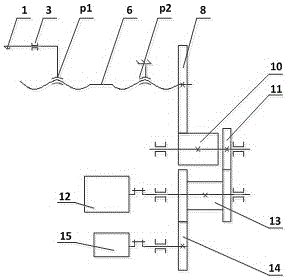
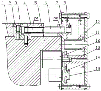
[0021] combine Figure 1 to Figure 4 , a spiral differential drive mechanism for ink knives for printing and coating partitions of metal sheets, used to drive ink knives for printing and coating partitions of metal sheets, and the ink knives for ink supply are composed of 32 ink knives (keyboard ink knives), each ink knife 1 is connected to a helical differential drive mechanism, and the helical differential drive mechanism includes an ink knife guide pair, a coaxial and same direction double-segment screw 6, a frame 7, a transmission gear set, a drive motor 12 and a half Closed loop position detector 15. The ink knife guide pair is used to connect the ink knife 1, the transmission gear set is arranged in the frame 7, the drive motor 12 and the semi-closed loop position detector 15 are all arranged on the frame 7, and one end of the coaxial and the same dire...


PUM


Abstract

The invention discloses a screw differential driving mechanism of an ink knife for supplying ink to areas during printing metal sheets. Each ink knife is connected with a screw differential driving mechanism. The screw differential driving mechanism comprises an ink knife guide pair, a coaxial same-direction double-section screw, a frame, a transmission gear set, a driving motor and a semi-closed-loop position detector; the ink knife guide pair is used for connecting with the ink knife; the transmission gear set is arranged inside the frame; the driving motor and the semi-closed-loop position detector are arranged on the frame; one end of the coaxial same-direction double-section screw is connected to the ink knife guide pair and is capable of achieving synchronous motion; the other end of the coaxial same-direction double-section screw passes through the frame and is connected to the transmission gear set; and the driving motor and the semi-closed-loop position detector are connected to the transmission gear set separately. Through the screw differential driving mechanism, a differential screw pair and the transmission gear set are used for transmitting power, so that the micro-quantity feeding of the ink can be easily achieved, and the ink quantity adjustment accuracy is improved; and the ink is supplied to independent areas, so that the requirements on ink supply of different areas of printed products can be met to a maximum limit.

Description

technical field [0001] The invention belongs to the technical field of metal sheet printing and coating equipment, and in particular relates to a spiral differential drive mechanism for ink supply ink knives in partitions of metal sheet printing and coating. Background technique [0002] When printing and coating metal sheets, it is necessary to determine the amount of ink supply in the corresponding area according to the pattern distribution and color tone of the printed product, and the amount of ink supply is controlled by the gap between the ink knife and the ink roller (also called the opening of the ink knife). The ink knife of the ink supply system of the existing metal sheet printing and coating equipment (such as iron printing machine) is an elastic body with an overall structure. When adjusting, a simple screw mechanism is used to force the elastic body to deform to realize the change of the gap between the ink knife and the ink roller in different areas. In order ...

Claims


Application Information

Patent Timeline
Patent Type & Authority Applications(China)
IPC IPC(8): B41F31/13
CPCB41F31/13
Inventor 曹春平孙宇武凯丁武学王栓虎
Owner NANJING UNIV OF SCI & TECH
Learn More