
Novel decorative suspended ceiling

A new type of suspended ceiling technology, which is applied in covering/lining, building, building structure, etc., can solve the problems of differences in overall appearance effects, inability to play a decorative role, and destroying the interior decoration environment, etc., to achieve simple and easy composition and assembly methods Line, simple and easy On-site installation specifications, decorative pattern making simple effect

Inactive Publication Date: 2005-01-19
刘振利
View PDF0 Cites 1 Cited by
  • Summary
  • Abstract
  • Description
  • Claims
  • Application Information

AI Technical Summary

Problems solved by technology

However, the existing suspended ceilings have the following disadvantages: 1. The whole plate is hoisted on the wall, and the environmental conditions to be adapted are not the same due to the different materials selected (such as gypsum boards, wooden boards, etc.)
After a long time of use, due to the influence of environmental temperature, humidity and other factors, the board will inevitably undergo aging or oxidation reactions, and eventually there will be problems such as deformation, discoloration, cracking or partial shedding
If partial modification is carried out, it will directly cause the difference in the overall appearance effect; 2. If the overall plate is replaced, additional material costs will be required
The short service life and high update cost are not acceptable to customers; 3. If the overall plate is not updated, not only will it not be able to play a decorative role, but it will damage the interior decoration environment even more

Method used


Image

  • Novel decorative suspended ceiling
  • Novel decorative suspended ceiling
  • Novel decorative suspended ceiling

Examples


Embodiment 1

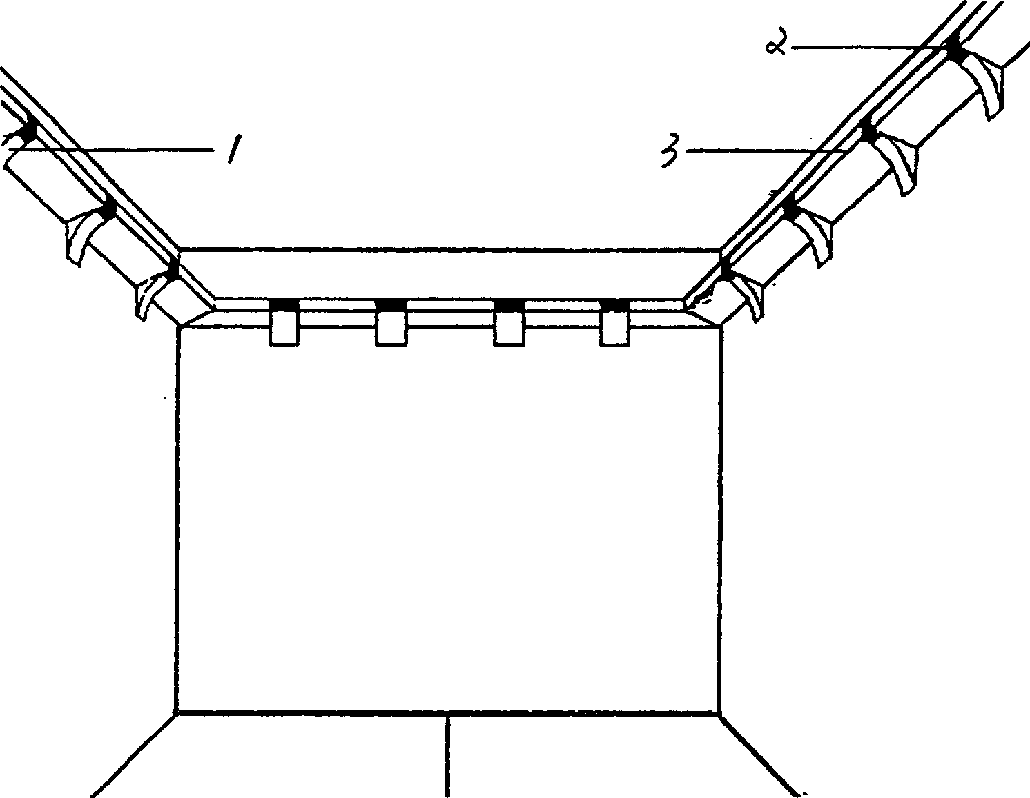
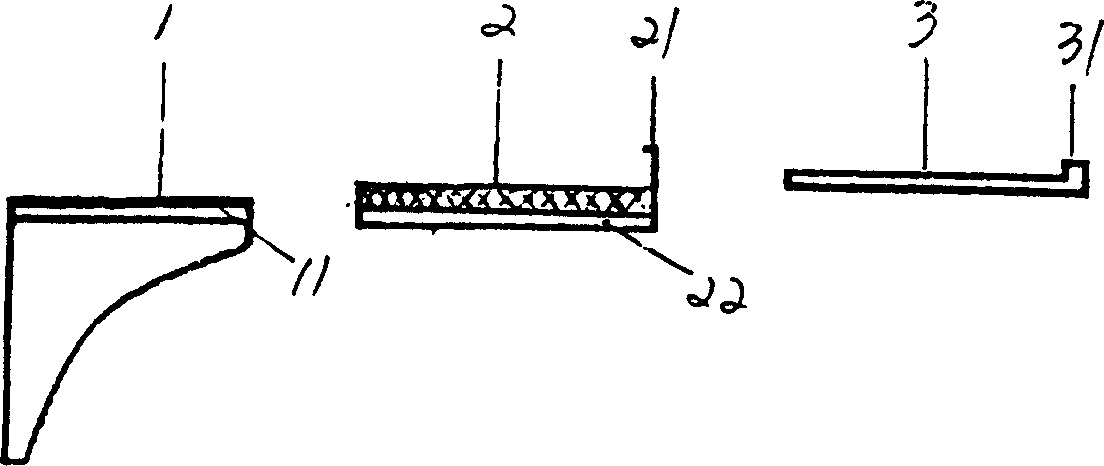
[0044] Embodiment 1, the novel decorative suspended ceiling of the present invention, includes a bracket 1 , a fixing plate holder 2 and a profile plate 3 .

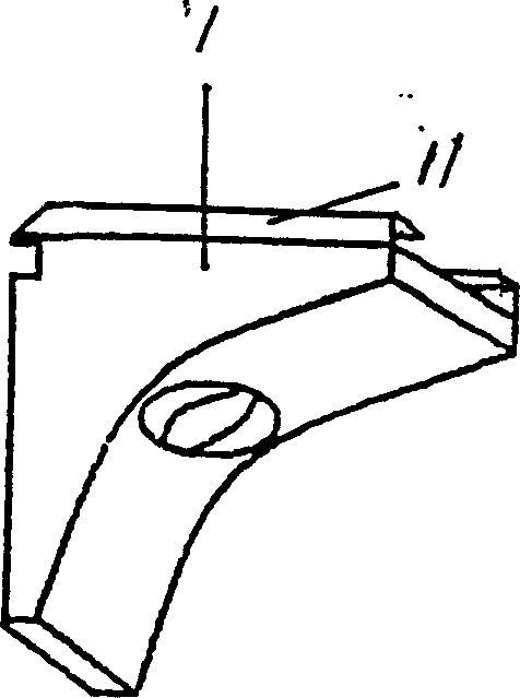
[0045] The bracket 1 has a top surface, two side surfaces, a front surface and a bottom surface. The interior between the top surface, front surface, both sides and the bottom surface of bracket 1 is a hollow part, and there is a screw hole on each side surface. The distance between the left and right ends of the blocks is slightly less than the width of the support, so that the support 1 can just cover the two wooden blocks.

[0046] The fixed plate holder 2 is designed with a horizontal plane and a flap 21 with a hemmed edge vertically upward along the horizontal direction.

[0047] There is a pair of symmetrical tenons 11 on the top of the bracket 1, and a pair of symmetrical longitudinal grooves 22 are designed on both sides of the fixed plate support 2. When installing, align the grooves 22 of the fixed plate suppo...

Embodiment 2

[0051] Embodiment 2, the novel decorative suspended ceiling includes brackets and profile plates.

[0052] The stand is designed with a horizontal top, side and bottom surfaces. The interior between the top surface of the bracket and the two sides is a hollow part, and there is a screw hole on each side. First fix the two wooden blocks on the wall, and then directly fix them on the two wooden blocks with screws. The left and right ends between the wooden blocks The spacing is slightly smaller than the width of the bracket, so that the bracket can just cover the two blocks.

[0053] The top surface of the support is designed with a folded seam masking plate vertically upward along the horizontal direction.

[0054] The profile plate is divided and processed into a standard piece with a length of 2.4 meters and a width of 0.2 meters, and has a folded edge shading plate vertically upward along the horizontal direction.

[0055] When installing on site, first fix several bracket...


PUM


Abstract

The invention relates to a decorative suspended ceiling, mainly comprising bracket, dead plate support and section material plate. The bracket is fixed on the wall, on which the dead plate support is mounted, and the section material plate is placed on the support directly. The improvement of the invention lies in sectional type structure composition and convent dependable assembling and mounting method.

Description

technical field [0001] The invention relates to a new type of decorative suspended ceiling, in particular to the improvement of the structure of the decorative suspended ceiling and its connection and fixing methods. Background technique [0002] At present, in urban residential quarters, families, hotels, restaurants, shopping malls, exhibition halls and other places, the indoor environment needs to be decorated to meet the pursuit of residents and consumers for environmental comfort and artistic atmosphere. Among them, the treatment and processing of walls and ceilings is particularly important. It is often necessary to increase the layering of the space through the ceiling decoration layer, and to combine plaster carvings or concave-convex patterns and color combinations on the board to achieve humanized and personalized decoration. style. [0003] The existing three-dimensional suspended ceiling decoration layer is usually located on the wall, near the position of the c...

Claims


Application Information

Patent Timeline
Patent Type & Authority Applications(China)
IPC IPC(8): E04F13/00
Inventor 刘振利周艳秋
Owner 刘振利
Learn More