Supercharge Your Innovation With Domain-Expert AI Agents!

Piezoelectric converter

A piezoelectric conversion and piezoelectric ceramic technology, which is applied to inking devices, circuits, piezoelectric devices/electrostrictive devices, etc. Effect of improving ejection characteristics

Inactive Publication Date: 2005-02-02
KYOCERA CORP
View PDF1 Cites 5 Cited by
  • Summary
  • Abstract
  • Description
  • Claims
  • Application Information

AI Technical Summary

Problems solved by technology

[0008] However, when the conventional piezoelectric transducer is cooled to room temperature after bonding, in the free area of ​​the piezoelectric actuator 92 corresponding to the cavity 911 that is not fixed on the substrate 91, that is, after adding Large buckling deformation (bending deformation) is likely to occur in the region where bending deformation occurs so as to protrude toward the cavity 911 when a voltage is driven.
In addition, when the buckling deformation occurs, the bending deformation when the driving voltage is applied in the same area is hindered, so there is a problem that the ejection characteristics of the ink droplets ejected from the nozzle portion 913 are degraded.
[0009] The reason for this is that the thermal stress generated due to the difference in thermal expansion coefficient between the metal forming the substrate 91 and the piezoelectric ceramic forming the piezoelectric ceramic layer 922

Method used


Image

  • Piezoelectric converter
  • Piezoelectric converter
  • Piezoelectric converter

Examples


Embodiment Construction

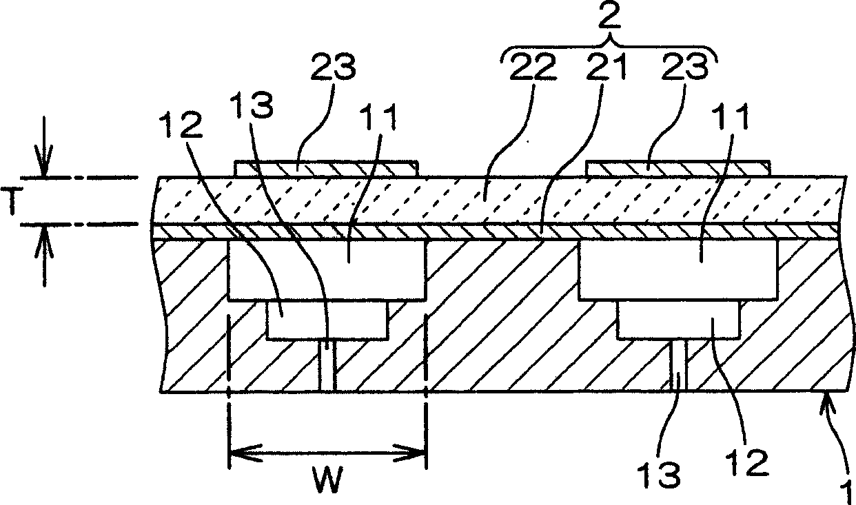
[0025] figure 1 It is a cross-sectional view showing an example of an embodiment of the piezoelectric conversion device of the present invention that can be ideally used as a piezoelectric inkjet head.

[0026] The piezoelectric transducing device in the illustration has a structure in which, on one side of a plate-shaped substrate 1 in which a plurality of cavities 11 for filling liquid are arranged along the surface direction, layers including a multi-layer structure and a structure covering the plurality of cavities are stacked. A conductive vibration plate 21 with a size of 11, a plate-shaped piezoelectric ceramic layer 22 having a size to cover a plurality of cavities 11, and a piezoelectric ceramic layer 22 having a size corresponding to each cavity 11 are separated corresponding to each cavity 11. The piezoelectric actuator 2 of a plurality of independent electrodes 23 .

[0027] The conductive vibrating plate 21 sandwiches the piezoelectric ceramic layer 22 together ...


PUM


Abstract

A piezoelectric converter comprising a piezoelectric actuator that includes a piezoelectric ceramic layer of thin plate shape being stacked on the surface of a substrate on the side thereof whereon cavities to be filled with a liquid are formed wherein, in order to prevent a significant buckling deformation from occurring in a region of the piezoelectric actuator that corresponds to the cavities of the substrate, the thickness T (mm) of the piezoelectric ceramic layer and maximum width W (mm) of the cavities in the direction of substrate surface are set so as to satisfy the relation: T >= (19.6 W + 5.5) X 10<-3>.

Description

technical field [0001] The invention relates to a piezoelectric conversion device for converting an electric signal into a pressure change of a liquid by utilizing the electro-deformation effect of piezoelectric ceramics. Background technique [0002] Piezoelectric transducers are used especially in piezoelectric inkjet heads for printing by ejecting liquid droplets in instant response inkjet printers. [0003] As described in Japanese Patent Laid-Open Publication JP-H11-34320 (1999), this piezoelectric transducer has a structure in which piezoelectric actuators 92 including image 3 ), that is, on one side of the plate-shaped substrate 91 that has a plurality of cavities 911 for filling ink arranged along the surface direction, there is a conductive vibrating plate 921 of a size that covers the plurality of cavities 911, and also has a covering A flat piezoelectric ceramic layer 922 having a size corresponding to the plurality of cavities 911 and a plurality of independent ...

Claims


Application Information

Patent Timeline
Patent Type & Authority Applications(China)
IPC IPC(8): B41J2/045B41J2/055B41J2/14H01L41/09H01L41/187
CPCB41J2202/11B41J2002/14266B41J2/14233B41J2/045
Inventor 吉村健一东别府诚
Owner KYOCERA CORP
Features
  • R&D
  • Intellectual Property
  • Life Sciences
  • Materials
  • Tech Scout
  • Unparalleled Data Quality
  • Higher Quality Content
  • 60% Fewer Hallucinations
Learn More