Piezoelectric element and liquid nozzle
A technology of piezoelectric elements and piezoelectric layers, which is applied in the direction of electrical elements, piezoelectric devices/electrostrictive devices, piezoelectric/electrostrictive/magnetostrictive devices, etc., and can solve the problems that piezoelectric films are easily damaged
- Summary
- Abstract
- Description
- Claims
- Application Information
AI Technical Summary
Problems solved by technology
Method used
Image

Examples
no. 1 approach
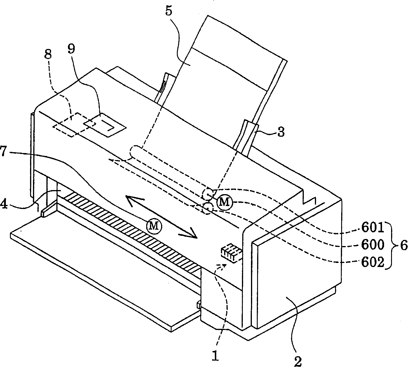
[0040] figure 1 is a schematic configuration diagram of a printer (an example of a liquid ejection device) using an inkjet type recording head (an example of a liquid ejection head) having a piezoelectric element manufactured by the method of this embodiment. In this printer, a tray 3 , a discharge port 4 , and operation buttons 9 are provided on a main body 2 . In addition, the main body 2 has an inkjet recording head 1 , a paper feeding mechanism 6 , and a control circuit 8 .
[0041] The ink jet recording head 1 has a piezoelectric element manufactured by the manufacturing method of the present invention. The inkjet recording head 1 can eject ink from the nozzles in response to an ejection signal supplied from the control circuit 8 .
[0042] The main body 2 is a frame of the printer, and a paper feeding mechanism 6 is arranged at a position where paper 5 can be supplied from a tray 3 , and an inkjet recording head 1 is arranged so as to print on paper 5 . The tray 3 is ...
no. 2 approach
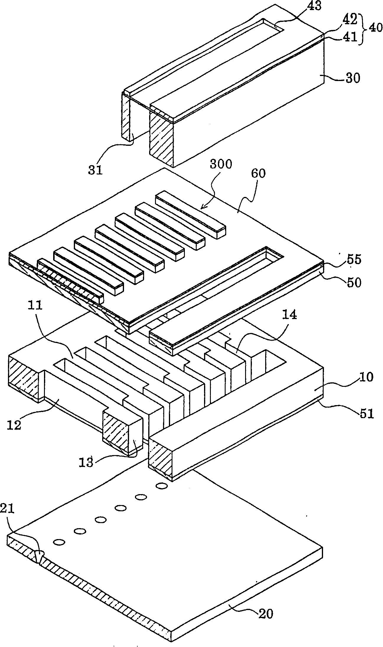
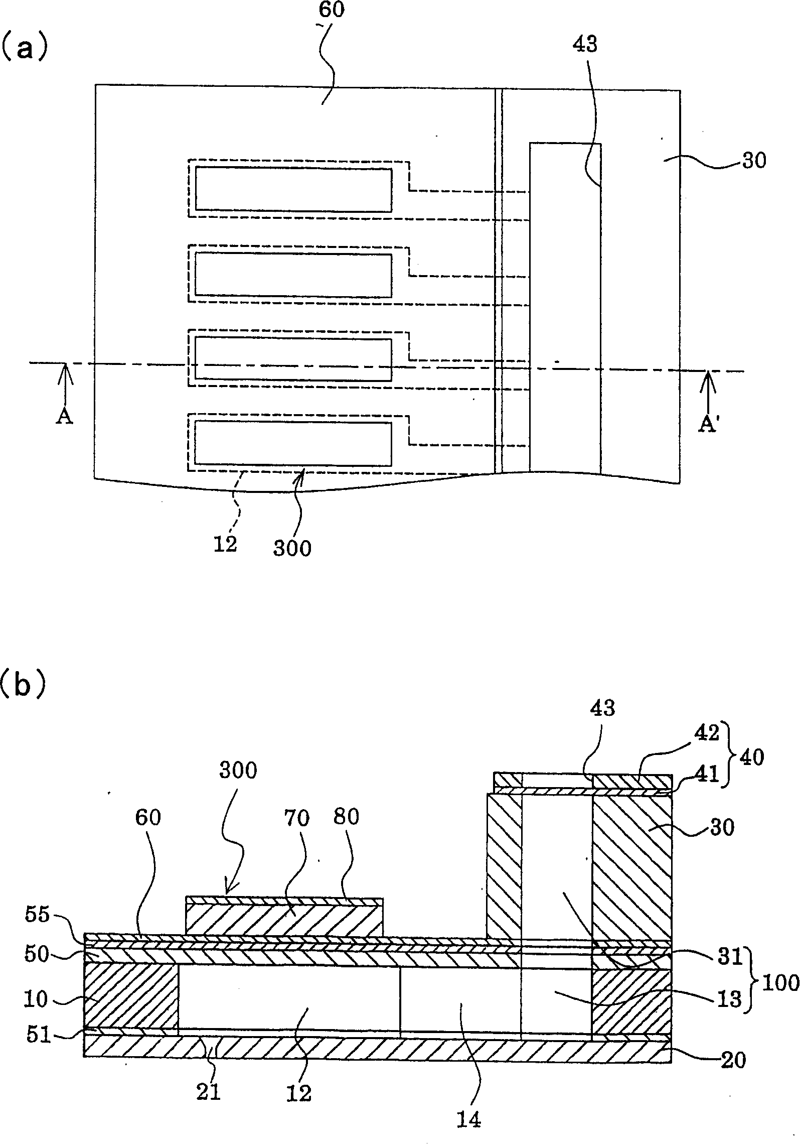
[0072] Figure 8 is a schematic exploded perspective view showing the recording head in the second embodiment, Figure 9 yes Figure 8 plan and B-B' section, Figure 10 It is a schematic diagram showing the layer structure of the piezoelectric element. In addition, the same code|symbol is attached|subjected to the same member as the member demonstrated in 1st Embodiment, and overlapping description is abbreviate|omitted.
[0073] This embodiment mode is another example of the layer structure of the piezoelectric element, specifically, as Figure 8 ~ Figure 10 As shown, the lower electrode films 60A constituting the piezoelectric element 300 are respectively patterned in the vicinity of both end portions of the pressure generating chambers 12 , and are continuously arranged along the parallel arrangement direction of the pressure generating chambers 12 . In addition, in the present embodiment, the end surface of the lower electrode film 60A in the region facing each pressur...
no. 3 approach
[0093] Figure 16 It is a plan view and a cross-sectional view of the ink jet recording head in the third embodiment.
[0094] This embodiment is an example in which a metal layer is provided on the vibrating film near the end of the piezoelectric film 70A, and is the same as the second embodiment except that the metal layer is provided. Specifically, as Figure 16 As shown, a metal layer 61 formed of the same layer as the lower electrode film 60A but not electrically conductive with the lower electrode film 60A is provided near the longitudinal end of the piezoelectric film 70A. In addition, the piezoelectric films 70A extend to a part of these metal layers 61 .
[0095] In addition, in the present embodiment, the metal film 61A provided near the end portion of the piezoelectric film 70A on the guide electrode 90 side is separately provided for each piezoelectric element, and the guide electrode is extended on the metal layer 61A. 90. On the other hand, the metal layer 61...
PUM
 Abstract
Description
Claims
Application Information
 - R&D
- Intellectual Property
- Life Sciences
- Materials
- Tech Scout
- Unparalleled Data Quality
- Higher Quality Content
- 60% Fewer Hallucinations
Browse by: Latest US Patents, China's latest patents, Technical Efficacy Thesaurus, Application Domain, Technology Topic, Popular Technical Reports.
© 2025 PatSnap. All rights reserved.Legal|Privacy policy|Modern Slavery Act Transparency Statement|Sitemap|About US| Contact US: help@patsnap.com