Ultrasonic transmitter-receiver and ultrasonic flowmeter
An ultrasonic and receiver technology, applied in the field of ultrasonic flowmeter, can solve problems such as finding difficulties
- Summary
- Abstract
- Description
- Claims
- Application Information
AI Technical Summary
Problems solved by technology
Method used
Image
Examples
Embodiment approach 1
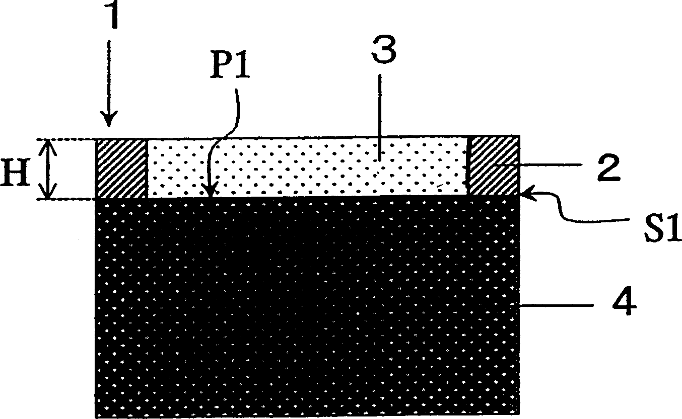
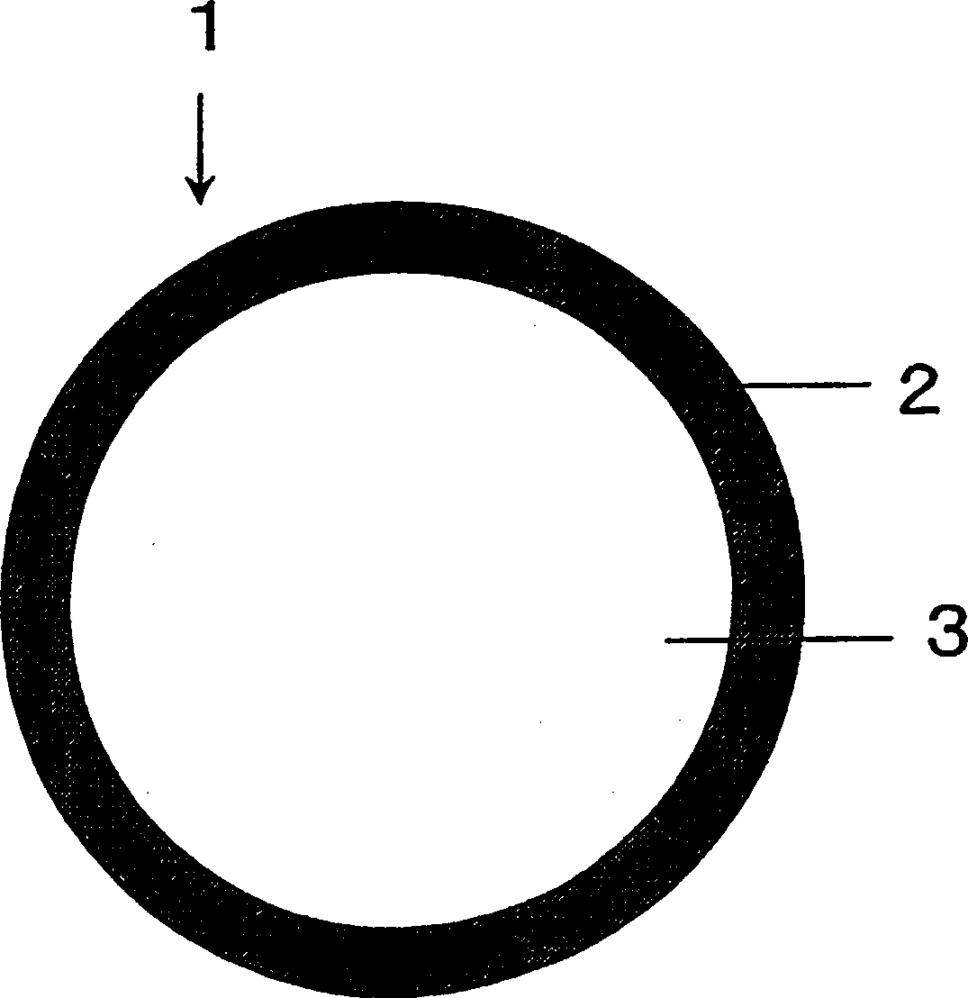
[0157] figure 1 A cross-section of an ultrasonic transmitter-receiver (ultrasonic vibrator) in the first embodiment of the present invention is shown. The illustrated ultrasonic transmitter-receiver 1 has a piezoelectric body 4 , an acoustic matching layer 3 provided on the piezoelectric body 4 , and a protector 2 fixed to the piezoelectric body 4 .
[0158] The piezoelectric body 4 is made of a material having piezoelectric properties, and is polarized in the thickness direction. Electrodes (not shown) are provided on the upper and lower surfaces of the piezoelectric body 4 , and ultrasonic waves are emitted based on the voltage applied to the electrodes. Furthermore, when ultrasonic waves are received, a voltage signal is generated between the electrodes. In the present invention, the material of the piezoelectric body 4 is arbitrary, and known materials can also be used.
[0159] The height H of the protective portion 2 based on the main surface (ultrasonic transmitting...
no. 2 approach
[0197] refer to Figure 5 A second embodiment of the present invention will be described. In this embodiment, the protection part and the piezoelectric body are integrated. Specifically, a concave portion 5 a is formed in the central portion of the principal surface of the piezoelectric body 5 , and a part 5 b of the piezoelectric body 5 is used as a protection portion. In other words, a part 5b of the piezoelectric body 5 functions as a protecting portion, and the protecting portion is integrally formed with the piezoelectric body.
[0198] Figure 5 The ultrasonic transmitter receiver is made by the following method.
[0199] First, after preparing the piezoelectric body 5 subjected to the polarization treatment, one surface (principal surface) of the piezoelectric body 5 is processed to form the concave portion 5a. The processing for forming the concave portion 5a can be performed by an end mill or a sandblasting equipment. The depth of the recessed part 5a corresponds...
no. 3 approach
[0205] refer to Figure 8 A third embodiment of the present invention will be described.
[0206] The characteristic point of this embodiment is that it has the structural support body 6 . Figure 8 The shown support body 6 is provided with a disk-shaped support portion 6 a for fixing the acoustic matching layer 3 and the like, and a cylindrical portion 6 b extending continuously in the axial direction from the disk-shaped support portion. The end section of the cylindrical part is bent into an "L" shape so that it can be easily fixed on the board 60 for shielding and other devices.
[0207] On the surface of the support portion 6a of the structural support body 6, the acoustic matching layer 3 and the protection portion 2 are arranged, and the piezoelectric body 4 is arranged on the back surface of the support portion 6a. That is to say, the piezoelectric body 4 and the acoustic matching layer 3 are respectively provided at opposing positions sandwiching the structural suppor...
PUM
 Abstract
Description
Claims
Application Information
 - R&D
- Intellectual Property
- Life Sciences
- Materials
- Tech Scout
- Unparalleled Data Quality
- Higher Quality Content
- 60% Fewer Hallucinations
Browse by: Latest US Patents, China's latest patents, Technical Efficacy Thesaurus, Application Domain, Technology Topic, Popular Technical Reports.
© 2025 PatSnap. All rights reserved.Legal|Privacy policy|Modern Slavery Act Transparency Statement|Sitemap|About US| Contact US: help@patsnap.com


