
Ball-planting device for making several tin balls stick to chip

A chip and ball-mounting technology, applied in electrical components, semiconductor/solid-state device manufacturing, semiconductor devices, etc., can solve problems such as inability to guarantee solder balls, time-consuming, eye fatigue for maintenance personnel, etc.

Inactive Publication Date: 2005-02-16
HTC CORP
View PDF0 Cites 3 Cited by
  • Summary
  • Abstract
  • Description
  • Claims
  • Application Information

AI Technical Summary

Problems solved by technology

Generally speaking, it takes an average of 10 to 15 minutes for a skilled maintenance personnel to spread the solder balls on all the solder pads on the surface of the ball grid array package. Staring at the BGA package for a long time will cause eye fatigue for maintenance personnel, so that it cannot be guaranteed that each solder ball implanted back into the BGA package can be accurately implanted on the corresponding soldering pad

Method used


Image

  • Ball-planting device for making several tin balls stick to chip
  • Ball-planting device for making several tin balls stick to chip
  • Ball-planting device for making several tin balls stick to chip

Examples


Embodiment Construction

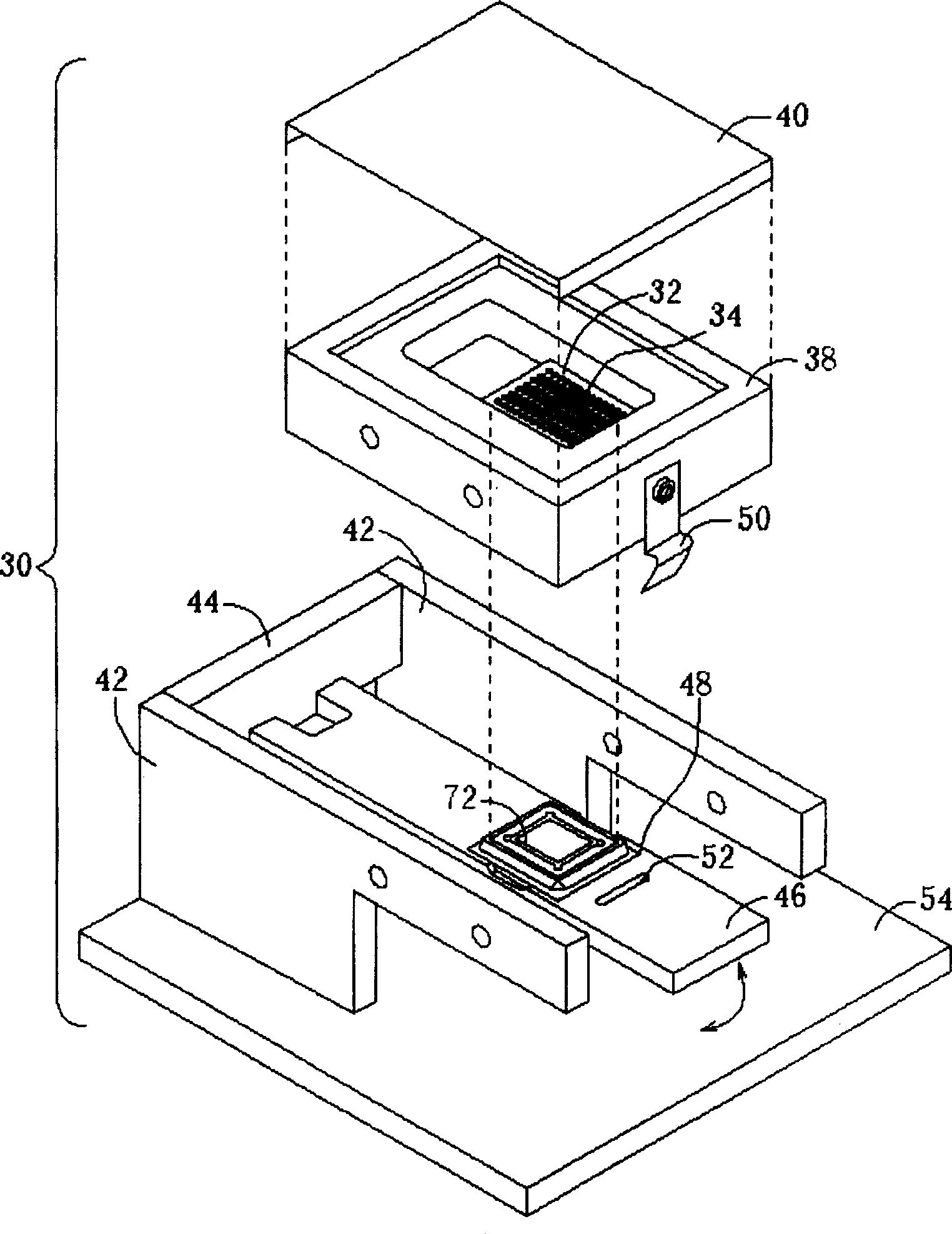
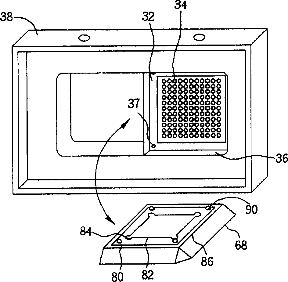
[0036] Please refer to figure 2 , figure 2 It is a schematic diagram of the table-top ball planting device 30 of the present invention. The ball planting device 30 is used to stick a plurality of solder balls with a diameter of 0.35 to 0.7 mm on a chip 72, and the chip 72 is coated with a thin layer of solder paste ( flux) and the like, which are used to adhere the solder balls implanted by the ball planting device 30 to the chip 72 . The ball planting device 30 includes a perforated plate 32 with a plurality of bead holes 34, each of which is used to accommodate a solder ball, and a locator 36 (shown in image 3 ), arranged under the perforated plate 32, used to fix the chip 72 under the perforated plate 32 to ensure that the positions of a plurality of cloth bead holes 34 on the perforated plate 32 can accurately correspond to a plurality of solder balls that should be implanted The positions on the chip 72 and a ball well 38 are used to load the plurality of solder ball...


PUM


Abstract

The device includes porous plate and a localizer. There are multiple holes for allocating beads, and each bead is utilized for accommodating a tin ball. The localizer is utilized for fixing the chip under the porous plate. The chip coated by a layer of adhesion agent adheres tin balls in each hole.

Description

technical field [0001] The invention provides a ball planting device, especially a ball planting device for adhering a plurality of solder balls to a chip. Background technique [0002] In recent years, with the rapid development of electronic technology and the emergence of LSI, VLSI, and ULSI, the density of a single silicon chip has been continuously increased. Due to the sharp increase in the number of I / O pins, the power consumed by each silicon chip has also increased. Therefore, the previous dual-line package (Dualin-line Package, DIP), and even the quad flat package (Quad Flat) Package, QFP) can no longer meet the actual needs, but the appearance of Ball Grid Array Package (BGA Package) fills this gap in time. [0003] Please refer to figure 1 , figure 1 It is a schematic cross-sectional view of a conventional ball grid array package 10. The ball grid array package 10 includes a substrate 12, and the substrate 12 includes a copper trace layer (Cu trace layer) 16 d...

Claims


Application Information

Patent Timeline
Patent Type & Authority Applications(China)
IPC IPC(8): H01L21/28H01L21/60
Inventor 杨军威
Owner HTC CORP
Learn More