Reliably connected door holder
A door suction, reliable technology, applied in the door suction. It can solve the problems of unreliable door suction device and failure of door suction fixing effect, and achieve the effect of solving unreliable connection, simple structure and reliable connection.
- Summary
- Abstract
- Description
- Claims
- Application Information
AI Technical Summary
Problems solved by technology
Method used
Image

Examples
Embodiment Construction
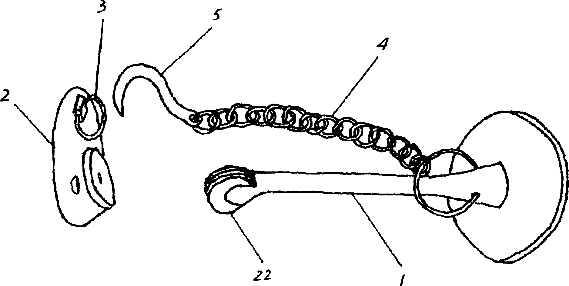
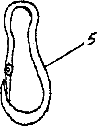
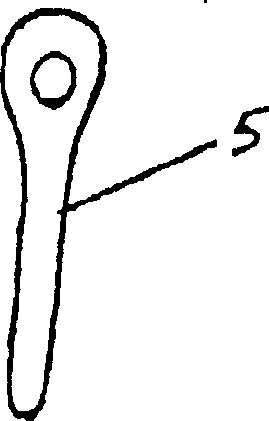
[0021] attached figure 1 It is the cube structure of the first specific embodiment of the present invention. This kind of reliable door stopper includes a pillar 1 on the wall, and a magnet 22 on the front end of the pillar 1 on the door. In addition, there is also a mechanical connection mechanism between the support 1 and the suction disk 2 that can ensure reliable connection. The mechanical connection mechanism includes a connecting ring 3 arranged on the side body of the suction disc 2, and a connecting hole 3 may also be provided, one end of which is connected to the flexible piece chain 4 on the pillar 1, and the other end of the chain is provided with a flexible part chain 4. The connector hook 5 hooked with the connecting ring 3 on the suction disc 2, the connector 5 can also be a latch or a carabiner, such as figure 2 , 3 As shown, in addition to using the principle of magnetic attraction to fix and connect the door, the utility model can also effectively ensure th...
PUM
 Abstract
Description
Claims
Application Information
 - Generate Ideas
- Intellectual Property
- Life Sciences
- Materials
- Tech Scout
- Unparalleled Data Quality
- Higher Quality Content
- 60% Fewer Hallucinations
Browse by: Latest US Patents, China's latest patents, Technical Efficacy Thesaurus, Application Domain, Technology Topic, Popular Technical Reports.
© 2025 PatSnap. All rights reserved.Legal|Privacy policy|Modern Slavery Act Transparency Statement|Sitemap|About US| Contact US: help@patsnap.com