
Tyre mould

A mold and tire tread technology, applied in the field of tire manufacturing, can solve problems such as difficulty in maintaining the distribution of metal sheets, hindering the opening and closing movement of the mold, and flashing

Inactive Publication Date: 2005-02-23
MICHELIN & CO CIE GEN DES ESTAB MICHELIN +1
View PDF3 Cites 5 Cited by
  • Summary
  • Abstract
  • Description
  • Claims
  • Application Information

AI Technical Summary

Problems solved by technology

There may be additional friction that hinders the opening and closing movement of the mold
Also it is difficult to keep the gaps between the metal sheets distributed as required
Therefore, flashing may occur where the gap between the metal sheets is greater than the rated gap

Method used


Image

  • Tyre mould
  • Tyre mould
  • Tyre mould

Examples


Embodiment Construction

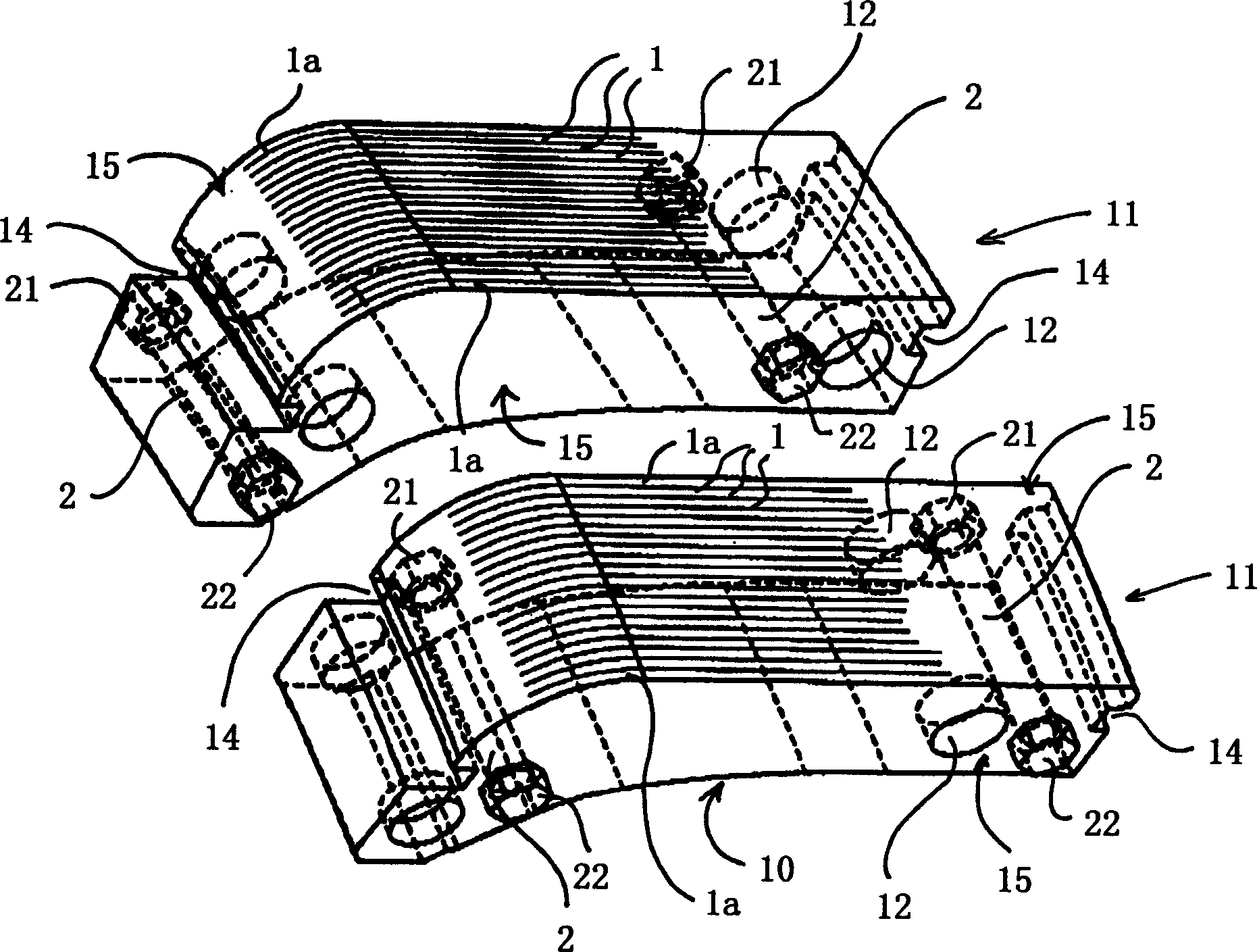
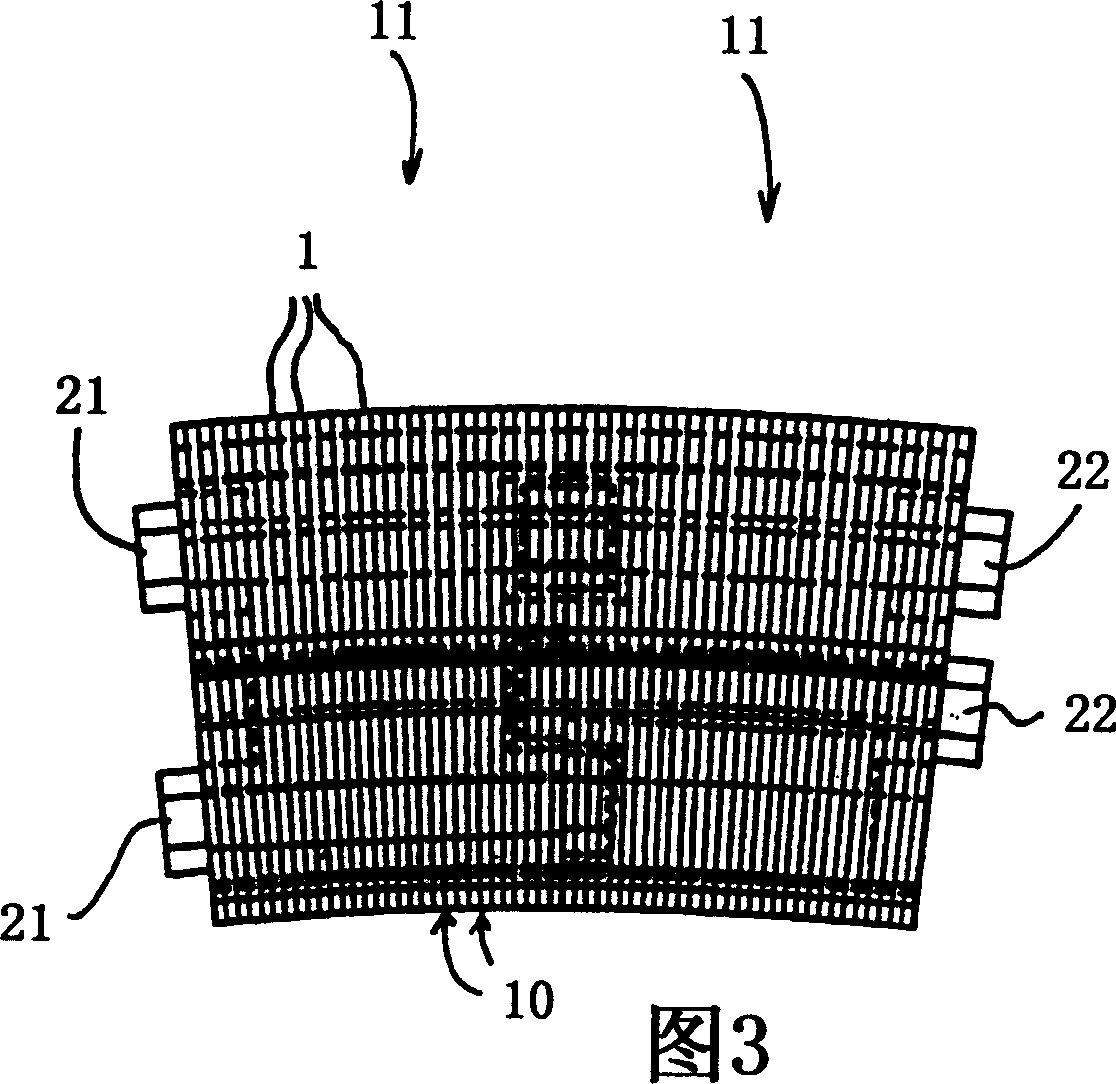
[0021] In the mold of this embodiment, the molding elements for molding the sheet-combined ring of the tread are metal sheets 1 adjacent to each other, with a thickness between 0.1 mm (preferably 0.5 mm) and 5 mm (see figure 2 ). Sheet composite rings consist of thousands of sheets of metal placed next to each other. This is a very advantageous method of making thin components with such mold characteristics. The thickness of the metal sheet corresponds to the resolution of the pattern determined by the mold. For example thin layers of steel may be used; they are preferably cut perpendicular to the plane of the curve defined by the tread pattern to be produced. Since the steel sheets are always cut perpendicularly, some surfaces of the tread pattern look like the steps of a staircase, which is the appearance characteristic of this technology. The sides of the metal sheets are preferably non-parallel to each other so that when they are put together they naturally fan out and...


PUM

PropertyMeasurementUnit
Thicknessaaaaaaaaaa

Abstract

The invention relates to a tyre mould comprising a laminated peripheral ring. The aforementioned laminated peripheral ring consists of adjacent sheets (1) having a narrow thickness which are stacked in the circumferential direction. Said sheets are grouped together in sectors (11) to form a one-piece sub-assembly.

Description

technical field [0001] This invention relates to the manufacture of tires, and more particularly to the molding of their treads. Background technique [0002] Patent application EP 0 569 909 describes a mold in which a large number of transversely arranged metal sheets is prepared for molding a tread. A set of cut edges of all sheet metal forms the molding surface. The transverse metal plates extend from one shoulder of the tire to the other, the patent application EP 0 860 260 proposes to keep the metal plates strictly radial, since the middle metal plate itself engages in the groove of the support ring and thus can is correctly directed. [0003] In all cases envisaged, the opening and closing of such molds must provide radial displacement of all the metal sheets constituting the laminar constituent ring. There may be additional friction present, thereby hindering the opening and closing movement of the mold. Furthermore it is difficult to keep the gaps between the met...

Claims


Application Information

Patent Timeline
IPC IPC(8): B29C33/10B29C33/02B29C35/02B29D30/06B29L30/00
CPCB29D2030/0617B29D30/0606B29C33/30
Inventor A·索拉里奥
Owner MICHELIN & CO CIE GEN DES ESTAB MICHELIN
Features
  • Generate Ideas
  • Intellectual Property
  • Life Sciences
  • Materials
  • Tech Scout
  • Unparalleled Data Quality
  • Higher Quality Content
  • 60% Fewer Hallucinations
Learn More