Supercharge Your Innovation With Domain-Expert AI Agents!

Back light module

A technology of backlight components and light guide plates, applied in optics, nonlinear optics, instruments, etc., can solve problems such as poor structural rigidity and difficulty in designing thin models

Inactive Publication Date: 2005-03-02
AU OPTRONICS CORP
View PDF0 Cites 1 Cited by
  • Summary
  • Abstract
  • Description
  • Claims
  • Application Information

AI Technical Summary

Problems solved by technology

[0008] However, in image 3 Among them, although the blocking wall 31a is designed to prevent the lamp tube 32 from breaking, only the backlight assembly 30 is carried by the plastic shell 31, because the thickness of the plastic material is limited by injection molding, and if the thickness of the plastic material is thin, the structural rigidity is poor, so Based on the above considerations, it is not easy to design thin products

Method used


Image

  • Back light module
  • Back light module
  • Back light module

Examples


Embodiment Construction

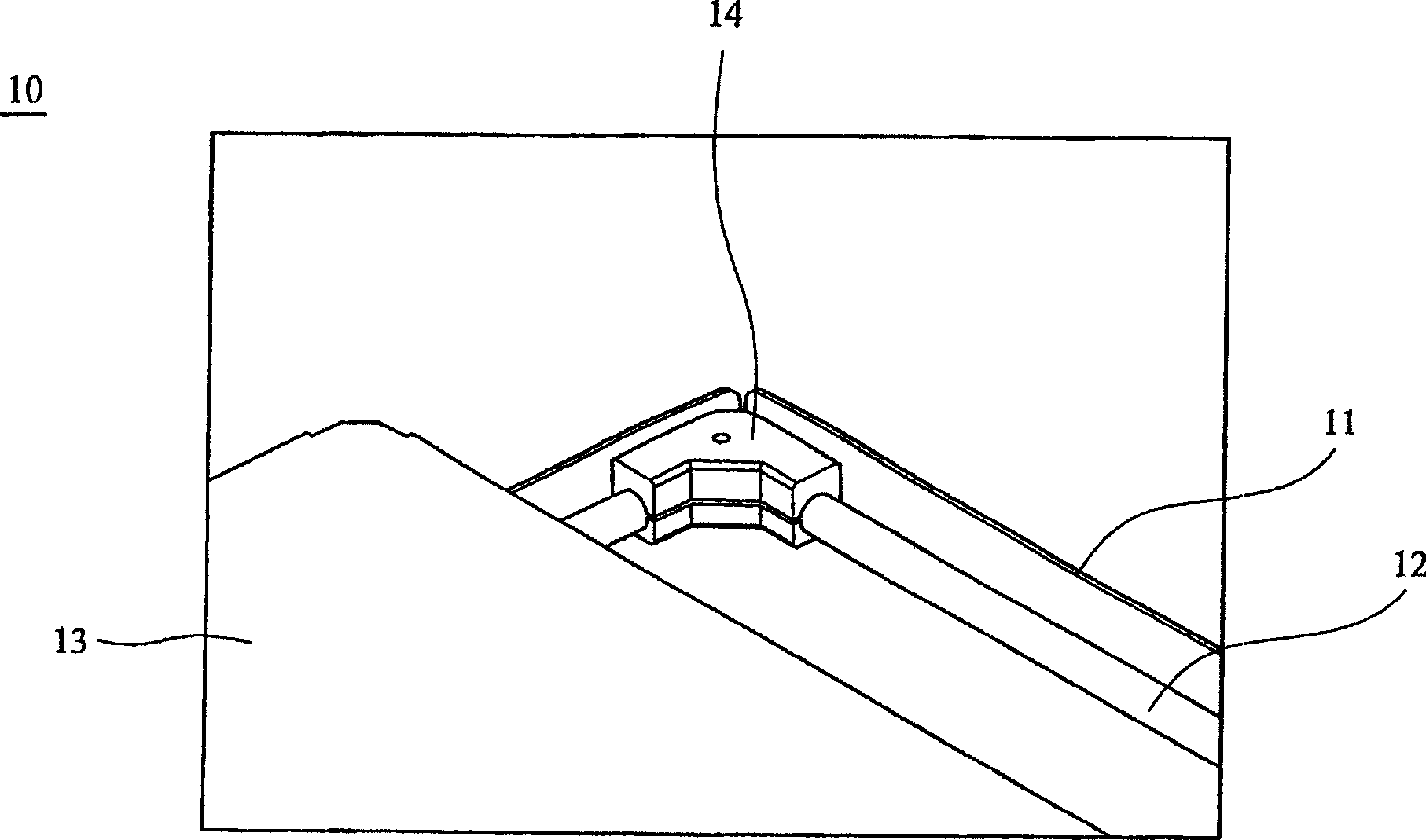
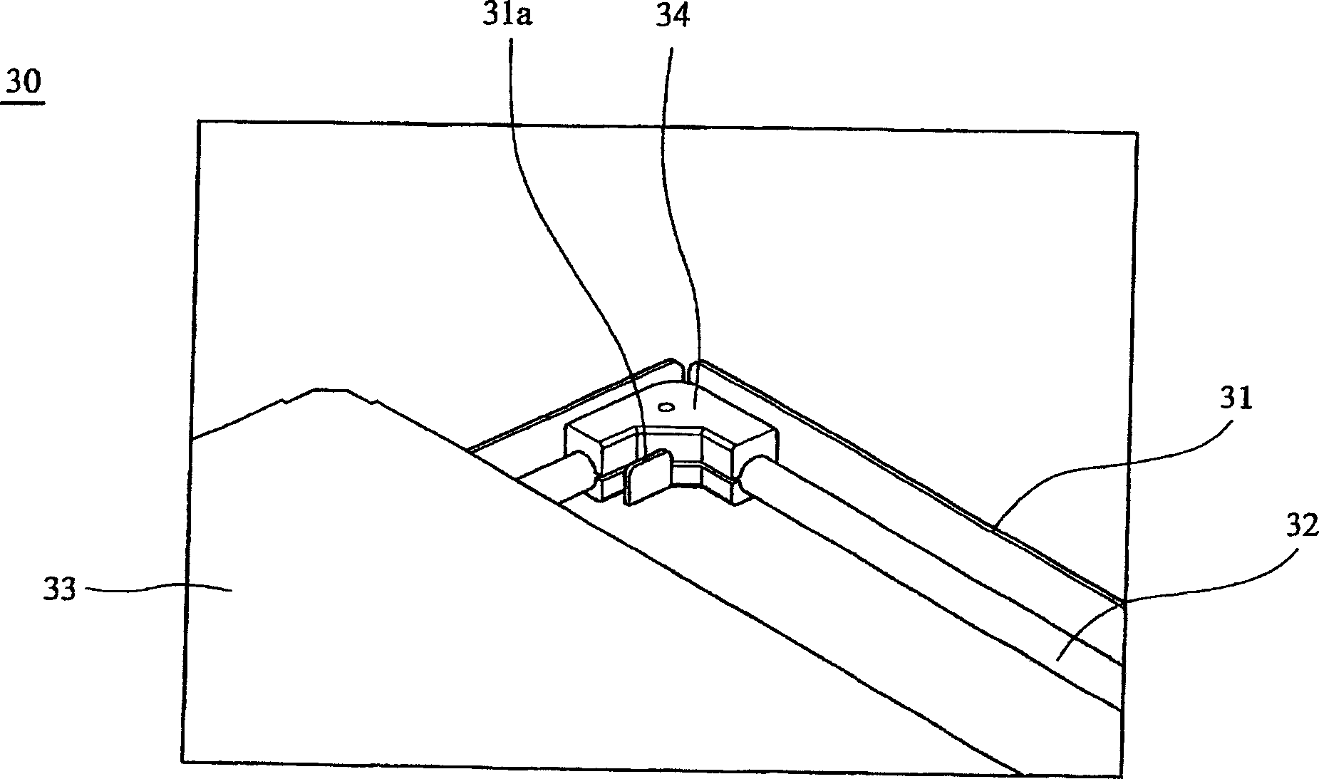
[0053] refer to Figure 4a , the backlight assembly 100 of the present invention includes: a bottom case 110, a frame 120, a light guide plate 130, a lamp tube 140, two fixing members 150, and a reflector 160. It should be understood that there are still Since other components are not directly related to the present invention, their descriptions are omitted here.

[0054] The bottom case 110 is made of metal, such as iron, and is used to carry other components. The frame 120 is made of plastic, which is disposed on the bottom case 110 and forms a blocking wall 121 at a corner.

[0055] The light guide plate 130 is disposed on the bottom case 110 and is located in the frame 120. The light guide plate 130 has four sides 130a, 130b, wherein the side 130a is in contact with the frame 120, and the side 130b is in close contact with the lamp tube 140, as Figure 4b Shown; Also, the shape of the retaining wall 121 of the frame 120 corresponds to the shape of the corner 130c between ...


PUM


Abstract

The invention is a backlight module, including a bottom case, a frame, a light guide plate and a tube, where the frame is arranged on the bottom case and has a baffle, the light guide plate is situated in the frame and arranged on the bottom case, the tube is combined with the light guide plate in a mode of forming a gap from the light guide plate, and the baffle of the frame is situated in the gap.

Description

technical field [0001] The invention relates to a backlight assembly, in particular to a backlight assembly capable of effectively positioning a lamp tube and a light guide plate. Background technique [0002] In the backlight assembly, the light tube as the light source must be close to the light guide plate to achieve the best light efficiency. However, because the light tube is fragile, it is necessary to pay great attention to the positioning between the light guide plate and the light tube during assembly. [0003] Known backlight assembly 10 such as figure 1 As shown, it includes an iron shell 11, an L-shaped lamp tube 12, a light guide plate 13, and a rubber cap 14. The L-shaped lamp tube 12 and the light guide plate 13 are all arranged in the iron shell 11. The light source at the corner of the L-shaped lamp tube 12 is unnecessary in the backlight assembly 10, so the L-shaped lamp tube 12 is not in close contact with the light guide plate 13 at the corner, and a rub...

Claims


Application Information

Patent Timeline
Patent Type & Authority Applications(China)
IPC IPC(8): G02F1/1335G02F1/13357
Inventor 郭汉斌
Owner AU OPTRONICS CORP
Features
  • R&D
  • Intellectual Property
  • Life Sciences
  • Materials
  • Tech Scout
  • Unparalleled Data Quality
  • Higher Quality Content
  • 60% Fewer Hallucinations
Learn More