Control valve for automatic preventing body fluid regurgitation preventing
An automatic prevention and flow control technology, applied in the direction of the valve, can solve the problems of drainage fluid reflux, retrograde infection, etc., and achieve the effect of preventing retrograde infection, low price and good economic benefits
- Summary
- Abstract
- Description
- Claims
- Application Information
AI Technical Summary
Problems solved by technology
Method used
Image


Examples
Embodiment 1
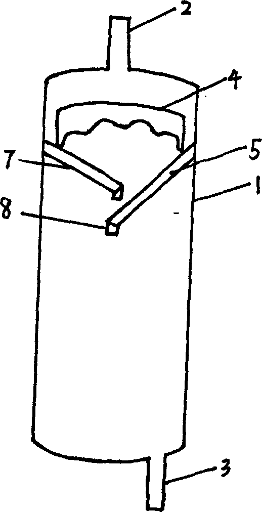
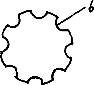
[0023] Embodiment 1: as figure 1 , figure 2 , image 3 As shown, the automatic body fluid reflux control valve includes a valve body cavity 1, a body fluid inlet 2 is provided at one end of the valve body cavity 1, a liquid discharge port 3 is provided at the other end, and a valve body switch is provided inside the valve body cavity 1 Part 4 and anti-reflux clip 5, the valve body switch part 4 is movably sealed at the entrance of the body fluid inlet 2, and the lower part of the movable valve body switch part 4 is provided with an anti-reflux clip 5, and the upper part of the valve body switch part 4 is Arc shape, its periphery is provided with groove 6. The anti-reflux clamp 5 is two interlaced plates 7, each plate 7 is a slope-shaped plate extending downward at a certain angle, and the top of the anti-reflux clamp 5 of each slope-shaped plate is in contact with the inner wall of the valve body cavity 1 fixed. The edge end of each slope-shaped plate is provided with eav...
Embodiment 2
[0024] Embodiment 2: as Figure 4 , figure 2 , image 3 As shown, the automatic body fluid reflux control valve includes a valve body cavity 1, a body fluid inlet 2 is provided at one end of the valve body cavity 1, a liquid discharge port 3 is provided at the other end, and a valve body switch is provided inside the valve body cavity 1 Part 4 and anti-reflux clip 5, the valve body switch part 4 is movably sealed at the entrance of the body fluid inlet 2, and the lower part of the movable valve body switch part 4 is provided with an anti-reflux clip 5, and the upper part of the valve body switch part 4 is Arc shape, its periphery is provided with groove 6. The anti-reflux clip 5 is a slope-shaped anti-reflux clip along the inner wall of the valve body cavity 1 , and its slope top 9 is fixed to the inner wall of the valve body cavity 1 . The anti-reflux clip 5 is an integral structure. The shape of the valve body cavity 1 can be a cavity with a circular bottom surface, an ...
Embodiment 3
[0025] Embodiment 3: as Figure 5 , figure 2 , image 3 As shown, the automatic body fluid reflux control valve includes a valve body cavity 1, a body fluid inlet 2 is provided at one end of the valve body cavity 1, a liquid discharge port 3 is provided at the other end, and a valve body switch is provided inside the valve body cavity 1 Part 4 and anti-reflux clip 5 are provided with a cylinder 10 at the upper end of the inner wall of the valve body cavity 1, and the valve body switch part 4 is movably sleeved on the cylinder 10. In order to prevent the position stability of the valve body switch member 4 in the valve body cavity 1 when the position of the automatic body fluid backflow prevention control valve is changed. The valve body switch part 4 is movable and sealed at the entrance of the body fluid inlet 2, and an anti-reflux clip 5 is provided at the lower part of the movable valve body switch part 4, and the upper part of the valve body switch part 4 is arc-shaped,...
PUM
 Abstract
Description
Claims
Application Information
 - R&D
- Intellectual Property
- Life Sciences
- Materials
- Tech Scout
- Unparalleled Data Quality
- Higher Quality Content
- 60% Fewer Hallucinations
Browse by: Latest US Patents, China's latest patents, Technical Efficacy Thesaurus, Application Domain, Technology Topic, Popular Technical Reports.
© 2025 PatSnap. All rights reserved.Legal|Privacy policy|Modern Slavery Act Transparency Statement|Sitemap|About US| Contact US: help@patsnap.com