Method of determining a three-dimensional velocity field in a volume
A velocity field, space technology, applied in fluid velocity measurement, devices using optical methods, velocity/acceleration/shock measurement, etc., can solve problems such as inapplicability and high cost
Inactive Publication Date: 2005-03-23
LAVISION
View PDF6 Cites 7 Cited by
- Summary
- Abstract
- Description
- Claims
- Application Information
AI Technical Summary
Problems solved by technology
Since the image substrates need to be washed one by one first, and a CCD camera is used to scan at a high cost, this method is not suitable for industrial applications that often require thousands of images as a statistical basis for the flow field. Be applicable
Method used
View moreImage
Smart ImageViewing Examples
Examples
Embodiment Construction
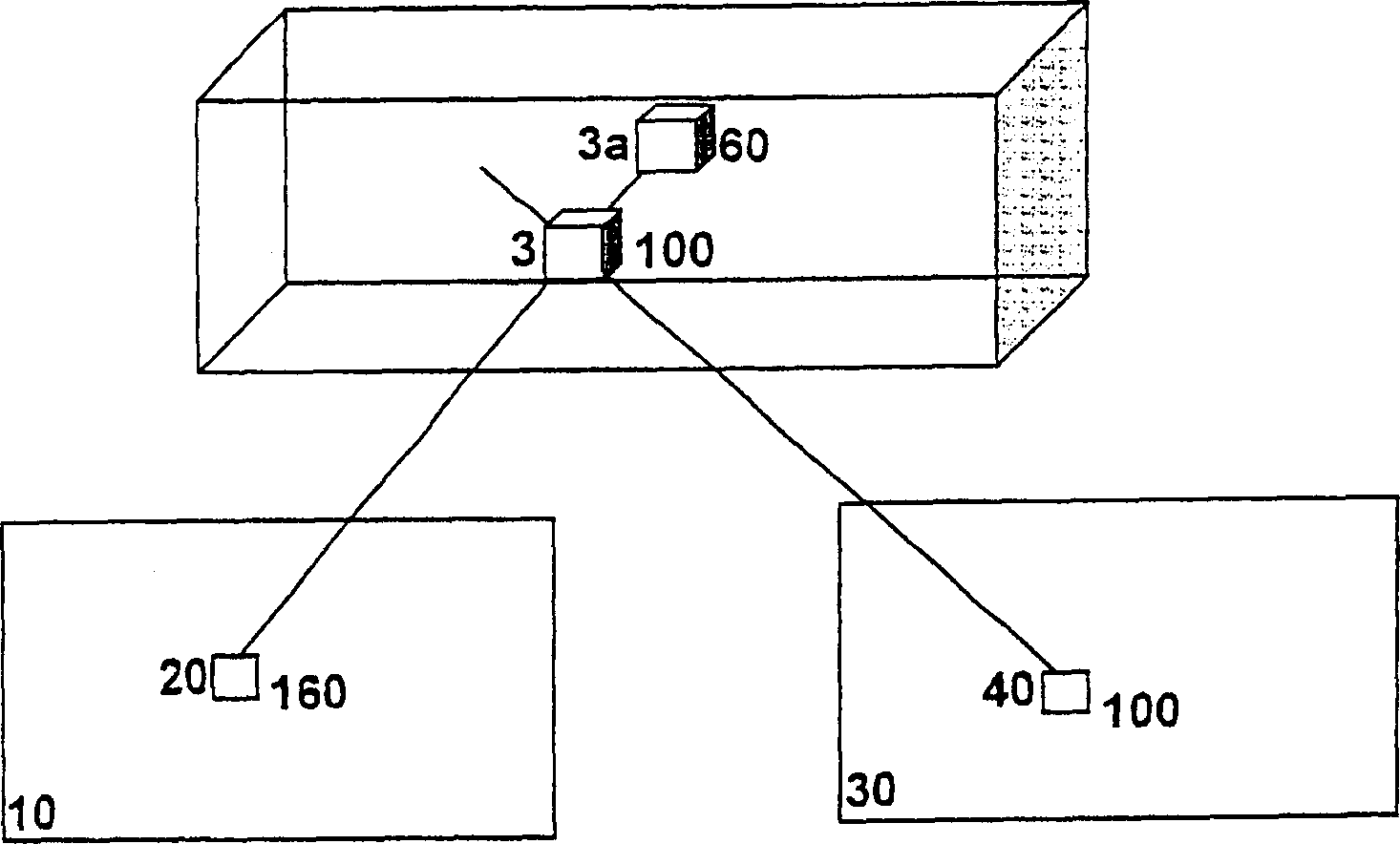
[0024] In the camera image of camera 10, pixel 20 receives light with an intensity count of 160 from volume elements (voxels) 3 and 3a. In the camera image of camera 30 , pixel 40 receives only light from volume element 3 with an intensity count of 100. When reconstructing voxel 3, the minimum intensity value in pixel 20 and pixel 40 is the correct voxel intensity with a count of 100.
Login to View More PUM
 Abstract
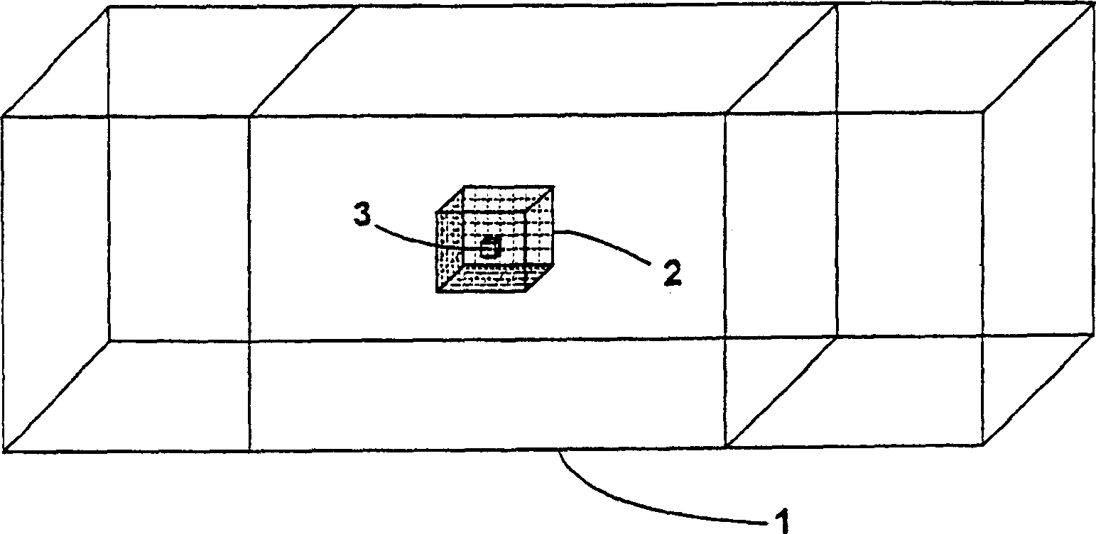
A method of determining a three-dimensional velocity field in a volume, the particles within the volume being excited to radiate by illuminating said volume, a) at least two cameras simultaneously image capturing the observation volume at two different instants of time (t1, t2) at least, b) the observation volume being divided into small volume elements (voxels), c) each voxel being projected at the location x, y, z onto the image points (xn, yn) of the at least two cameras using a projection equation, d) the intensity of all the voxels being reconstructed from the measured intensity of the respective ones of the associated image points (xn, yn), e) a plurality of voxels being combined to form an interrogation volume, f) the displacement vector (dx, dy, dz) being determined at the times (t1, t2) at the same location by a three-dimensional cross correlation of the two interrogation volumes.
Description
technical field [0001] The invention relates to a method for determining a three-dimensional velocity field in space. Background technique [0002] In the Particle Image Velocimetry (PIV) method (DE 19928698 A1) there is a standard method for measuring the velocity of gases or liquids, by which small particles are distributed in the gas or liquid flow, a thin observation plane usually with very fast The sequence is irradiated twice by the laser and imaged by a camera placed perpendicular to the observation plane, which takes two images in rapid sequence. These images captured by the camera are divided into small interrogation windows, which are cross-correlated at the two instants at which they are captured at position x, y in order to determine the two interrogation windows by the highest correlation peak The most likely displacement vector between (dx, dy). Therefore (dx, dy) are the two displacement vector components perpendicular to the camera viewing direction. The v...
Claims
Login to View More Application Information
Patent Timeline
 Patent Type & Authority Applications(China)
IPC IPC(8): G01P5/00G01P5/20G01P5/22G06T7/20
CPCG01P5/001G01P5/22G06T7/2086G06T7/285
Inventor B·维内克
Owner LAVISION
Features
- R&D
- Intellectual Property
- Life Sciences
- Materials
- Tech Scout
- Unparalleled Data Quality
- Higher Quality Content
- 60% Fewer Hallucinations
Learn More Browse by: Latest US Patents, China's latest patents, Technical Efficacy Thesaurus, Application Domain, Technology Topic, Popular Technical Reports.
© 2025 PatSnap. All rights reserved.Legal|Privacy policy|Modern Slavery Act Transparency Statement|Sitemap|About US| Contact US: help@patsnap.com


