Optical device for testing squint angle of faceplate

A technology of optical detection and oblique viewing angle, which is applied in the direction of using optical devices, measuring devices, and electromagnetic/magnetic devices to transmit sensing components, etc.

Inactive Publication Date: 2005-03-30
FAVITE
0 Cites 10 Cited by

AI-Extracted Technical Summary

Problems solved by technology

Among them, the method of using area scanning is to divide the whole panel into one area or multiple areas and scan, but scanning in this way has the following disadvantages: (1) the surface light source is difficult to be very uniform in a large area; (2) ) The flat field correction of surface light source inhomogeneity has a large amount of data, which makes it slower and more difficult to execute image digital signal processing (image DSP); (3) The algorithm for calculating im...

Method used

Please refer to FIG. 5b, which shows that after the reflector 30 rotates the angle θ, the backlight light source device 60 needs to be translated to a new position, so that the oblique angle of sight of the camera device 20 is aligned with the backlight l...

Abstract

The present invention relates to an optical detection equipment of oblique viewing angle of panel. It utilizes oblique viewing angle line scanning to detect a panel. Said equipment includes a frame, at least a pick-up device placed on said frame, a reflector placed on said frame and positioned under said pick-up device, and a panel carrier which is placed under said pick-up device and said reflector and is used for carrying panel to be tested. Said invented equipment can utilize the regulation of angle theta of included angle between said reflector surfeace and sight line of said pick-up device to make the oblique viewing angle of that the sight line of said pick-up device is reflected to the panel to be tested can be controlled, and said optical detection equipment can execute an oblique viewing angle line scanning process to detect the characteristics related to viewing angle or defect on said panel.

Application Domain

Television system detailsColor television details +2

Technology Topic

Sight lineEngineering +3

Image

  • Optical device for testing squint angle of faceplate
  • Optical device for testing squint angle of faceplate
  • Optical device for testing squint angle of faceplate

Examples

  • Experimental program(1)

Example Embodiment

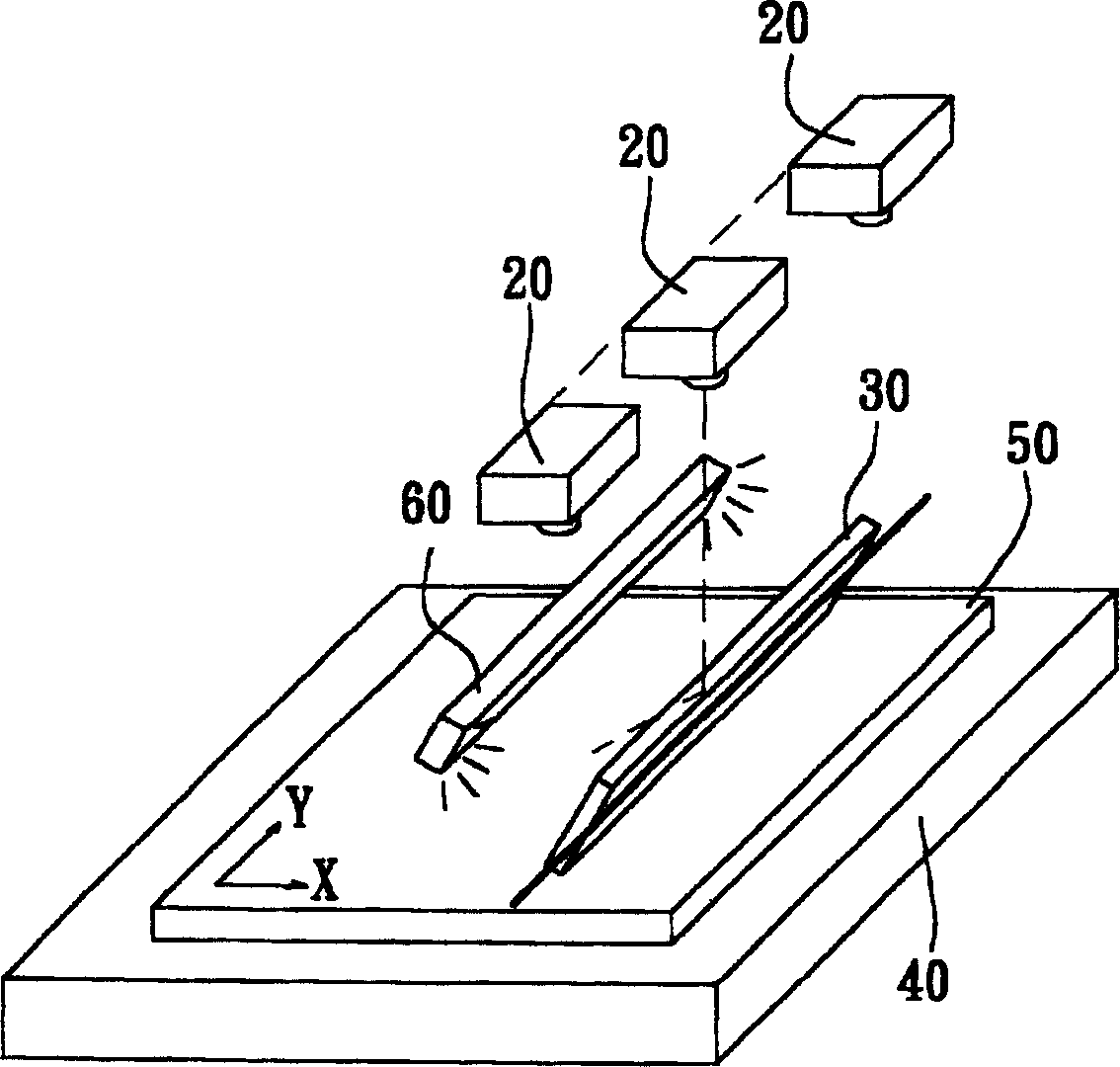
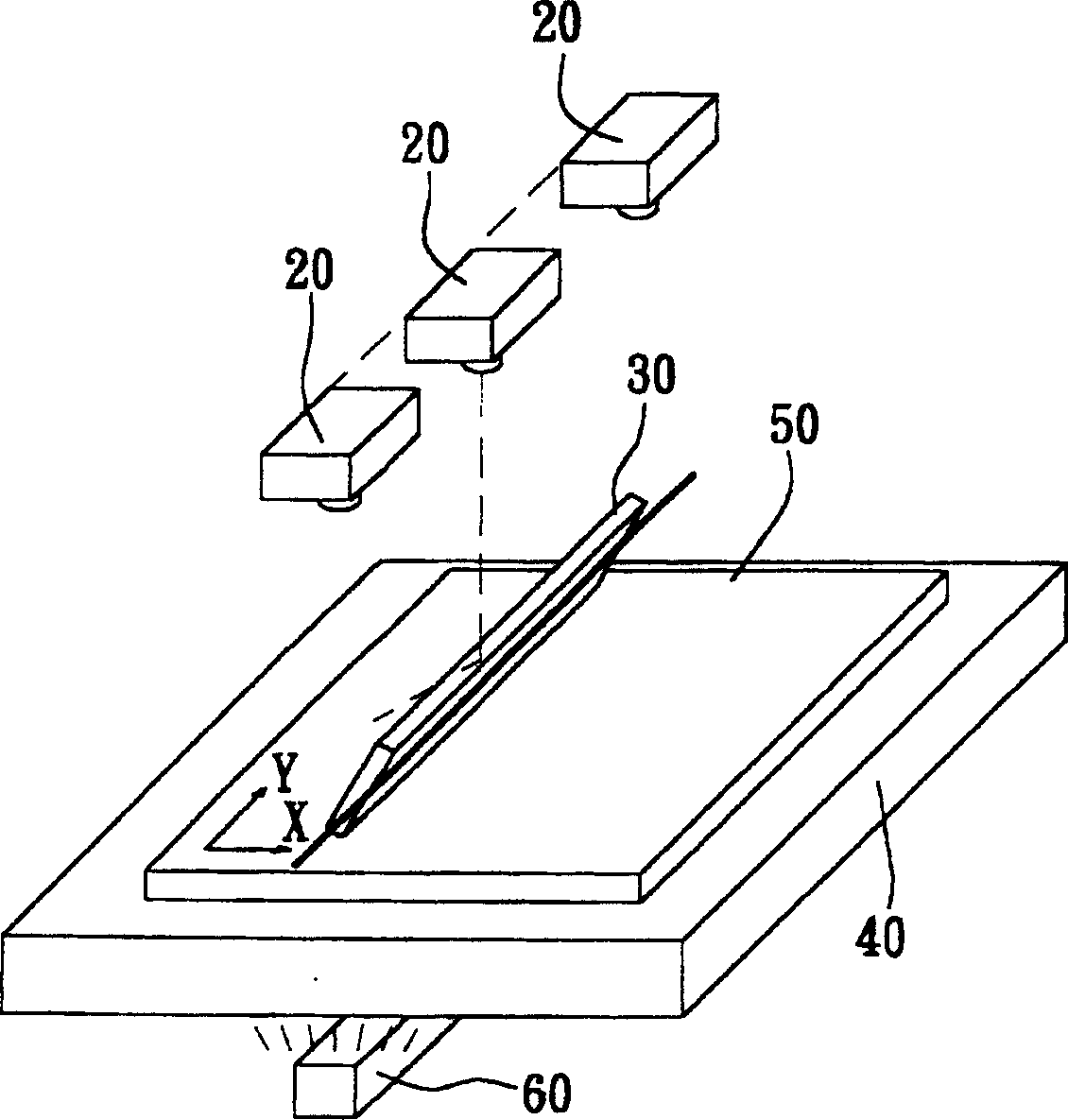
[0031] Please refer to Figure 2a , which shows a perspective view of an oblique viewing angle optical detection device for a panel according to the present invention. As shown in the figure, the oblique viewing angle optical detection device of the panel of the present invention is to detect the characteristics or defects of a panel by scanning the oblique viewing angle, which includes: a frame (not shown in the figure); at least one camera device 20; a A strip reflector 30 ; a linear lighting device 60 ; and a panel carrier 40 are combined.
[0032]Wherein, the frame is used to support the imaging device 20 and the mirror 30; the imaging device 20 is placed on the frame, and its number can be one to several and preferably one or a row of CMOS line scan cameras or one Or a row of CCD line scan cameras, and an angle θ is presented between the vertical line of sight of the imaging device 20 and the mirror surface of the reflector 30; The direction is parallel to the axial direction of the reflecting mirror 30; the reflecting mirror 30 is also placed on the frame and located below the imaging device 20, so that the vertical line of sight of the imaging device 20 (approximately perpendicular to the panel to be tested at 90° ° angle) after being reflected by the reflector 30, the viewing angle to the panel 50 to be tested is approximately 90°-2θ; and the panel carrier 40 is placed at a small distance below the reflector 30 to carry the The panel 50 to be tested. In order to adjust the angle θ of the reflector 30, the oblique viewing angle from the imaging device 20 to the panel to be tested is approximately 90°-2θ, and start to perform oblique viewing along the one-axis direction of the panel to be tested 50 Scanning, and after the panel 50 to be tested is scanned in one axis (such as the x-axis) direction, the frame, the imaging device 20, the line light source device 60 and the reflector 30 are aligned along the plane of the panel to be tested Rotate horizontally at an angle of 90° (or rotate the panel carrier 40 horizontally at an angle of 90°), and then perform oblique line scanning in the direction of another axis (eg, y-axis). In this way, the features or defects related to the oblique viewing angle of the panel 50 to be tested can be detected.
[0033] In addition, please refer to Figure 2b , which shows another schematic perspective view of an oblique viewing angle optical detection device for a panel according to the present invention. like Figure 2b As shown, if the panel to be tested 50 itself is translucent, then a line light source device 60 can be placed under the frame (not shown) and the panel to be tested 50 to provide the backlight (back-lit) required for line scanning. ) line source, wherein the axis of the line source device 60 is parallel to the axis of the reflector 30, and wherein the horizontal relative position of the line source device 60 and the reflector is related to the angle θ of the reflector 30.
[0034] Please refer to image 3 , which shows a partially enlarged schematic diagram of the incident angle and reflection angle of the reflector of the detection device of the present invention. As shown in the figure, it can be clearly seen that the approximately vertical line of sight (vertical line of sight) of the imaging device 20 of the present invention has an angle θ with the mirror surface of the reflecting mirror 30, and through the reflection of the reflecting mirror 30, the imaging device The angle between the line of sight of the oblique viewing angle of 20 and the panel 50 to be tested is approximately 90°-2θ. An oblique angle line scan is performed on the panel 50 to be tested through the oblique angle of approximately 90°-2θ.
[0035] Please refer to Figure 4 , which is a schematic diagram of the action of the imaging device and the mirror of the optical detection device according to a preferred embodiment of the present invention. As shown in the figure, the imaging device 20 of the present invention is placed on the frame, and can be adjusted by adjusting the oblique angle of sight of the imaging device 20 (that is, by adjusting the included angle θ between the imaging device and the mirror 30 ) to obtain different oblique viewing angle scanning effects. For the panel 50 to be tested, various oblique angle scans at different θ angles can be further performed along the x-axis and y-axis. In addition, at any fixed angle θ, the height of the z-axis of the imaging device 20 can be further adjusted so as to maintain a constant working distance (working distance), that is, no matter what the angle θ is, the distance from the imaging device 20 to the measured The working distance of the oblique viewing angle of the panel 50 can be kept constant by adjusting the z-axis height of the camera device 20 so as to obtain the same magnification and clear line scan effect.
[0036] Please refer to Figure 5a , which shows another schematic side view of the oblique viewing angle optical detection device of a panel according to the present invention. like Figure 5a As shown, when the mirror angle θ of the reflector 30 is zero degrees, the roughly vertical line of sight of the camera device 20 is roughly aligned with the centerline of the backlight light source device 60 .
[0037] Please refer to Figure 5b , which shows that after the reflector 30 is rotated by θ, the backlight source device 60 needs to be translated to a new position so that the oblique viewing angle of the camera device 20 is approximately aligned with the centerline of the backlight source device 60 . like Figure 5b As shown, the z-axis height of the imaging device 20 can be further adjusted to maintain a constant working distance, the same magnification and a clear line scan effect.
[0038] In addition, in the first embodiment (such as Figure 2a shown in ) and the second embodiment (as shown in Figure 2b , 5a and 5b), during line scanning, the camera device 20, the mirror 30 and the line light source device 60 move synchronously along the same axis, while the panel carrier 40 is fixed. Alternatively, during line scanning, the camera device 20 , the reflector 30 and the line light source device 60 are fixed, while the panel carrier 40 moves along an axis.
[0039] In addition, in the first embodiment (such as Figure 2a shown in ) and the second embodiment (as shown in Figure 2b , 5a and 5b), the mirror 30 can be a flat mirror (plate mirror) or a prism (prism).
[0040] Please refer to Image 6 , which is a schematic diagram of an imaging device of an optical detection device according to another preferred embodiment of the present invention. As shown in the figure, the optical detection device of the present invention includes: a frame (not shown in the figure); a rotation mechanism (rotation mechanism, not shown in the figure), wherein the rotation trajectory of the rotation mechanism (rotation trajectory) is in Image 6 Therefore, the reference number 70 indicates that the rotating mechanism can be fixed on the frame; a camera device 20 is placed in the rotating mechanism, and can rotate its oblique viewing angle by the rotating mechanism; and a panel carrier 40, whose It is placed under the imaging device 20 to carry a panel 50 to be tested. In order to adjust the oblique viewing angle between the imaging device 20 and the panel to be tested 50 by rotating the imaging device 20, and start to perform oblique viewing angle scanning, and after the panel to be tested completes the scanning in the x-axis direction, then execute Oblique viewing line scan in the y-axis direction. In addition, in this embodiment, because the rotation mechanism is designed to be located at any position in its rotation track 70, the oblique angle working distance between the imaging device 20 and the panel 50 to be tested is kept the same, so the imaging device The focusing of 20 only needs to be adjusted once at the beginning. And in this embodiment, the camera device 20 can adjust a proper oblique viewing angle without using any mirror.
[0041] In addition, if Image 6 In the embodiment shown in , during line scanning, the camera device 20 and the line light source device 60 can move synchronously along the same axis, while the panel carrier 40 is fixed. Alternatively, during line scanning, the camera device 20 and the line light source device 60 are fixed, while the panel carrier 40 can move along one axis.
[0042] In addition, the present invention also provides an oblique angle optical inspection method of a panel, which detects a feature or defect of a panel by scanning from an oblique angle line, which includes the following steps: providing a frame with at least one imaging device 20 on the frame , a line light source device 60 and a reflector 30 (step 1); a panel carrier 40 is provided, which is placed near the bottom of the imaging device 20 and the reflector 30, for carrying the panel 50 to be tested ( Step 2): Place a panel to be tested 50 on the panel carrier 40 (step 3); adjust the angle θ of the reflector 30 axially along the long axis of the reflector 30, so that the imaging device 20 and the to-be-tested The oblique viewing angle of the test panel 50 is approximately 90°-2θ (step 4); and start to perform oblique viewing line scanning along one axis (x-axis), and after the panel to be tested finishes scanning the x-axis direction, the The frame, together with the imaging device and mirror on it, is horizontally rotated at an angle of 90° along the plane of the panel to be tested, and then an oblique line scan in the y-axis direction is performed (step 5).
[0043] Wherein, under this step, the imaging device is one or a row of CMOS line scan cameras or one or a row of CCD line scan cameras. In this step 5, when starting to perform oblique angle line scanning, if the panel 50 to be tested is translucent, a line light source device 60 can also be provided under the frame to provide the backlight required for oblique angle line scanning light source. And during the online scanning, the camera device 20 , the reflector 30 and the line light source device 60 can move synchronously along the same axis, while the panel carrier 40 is fixed. Alternatively, during line scanning, the camera device 20 , the mirror 30 and the line light source device 60 are fixed, while the panel carrier 40 can move along one axis.
[0044] please refer again Figure 5a and 5b ,like Figure 5a As shown, when the mirror surface of the reflecting mirror 30 of the present invention forms an angle of 90° with the panel 50 to be tested, the vertical line of sight of the imaging device 20 is roughly aligned with the centerline of the line light source device 60 . like Figure 5b As shown, when adjusting the reflection angle θ of the reflection mirror 30 of the present invention, because the reflection mirror 30 and the line light source device 60 can be adjusted in conjunction, when adjusting the reflection angle of the reflection mirror 30, the line light source device 60 It will also move horizontally (for example, to the left), so that the oblique angle of view of the camera device 20 remains roughly aligned with the center line of the line light source device 60, so as to maintain the consistency of the line light source (Consistency), and then start to execute Oblique angle line scanning, and after the panel 50 to be tested is scanned along an axis (x-axis), the frame, together with the imaging device 20, the reflector 30 and the line light source device 60, are moved along the direction of the panel to be tested. The plane is rotated horizontally by an angle of 90°, and then an oblique line scan in the direction of the other axis (y-axis) is performed.
[0045] In addition to Figure 5a Among them, when the mirror surface of the reflecting mirror 30 of the present invention forms an angle of 90° with the panel 50 to be tested, a system flatfield correction (flatfield correction for the system) can be performed on the imaging device 20 and the line light source device 60 . Afterwards, the line light source device 60 is horizontally rotated at an angle of 90°, and the same spot illuminance (spot luminosity) is performed on each pixel of the camera device 20 by moving the line light source device. Flat field correction for the pixels. According to the two times of flat field calibration data, the flat field calibration of the imaging device 20 for the line light source device 60 is fully completed.
[0046] If used as Image 6 The rotation method and the rotation track 70 of a rotating mechanism (not shown in the figure) shown in the figure, the optical detection method of the oblique viewing angle of the panel of the present invention may include the following steps: providing a frame (not shown in the figure), on which there is a Rotating mechanism (not shown in the figure), and there is an imaging device 20 in the rotating mechanism, and the imaging device 20 can rotate its oblique viewing angle along its rotation track 70 in the rotating mechanism (step 1); provide a panel carrier 40, which is placed under the imaging device 20, in order to carry the panel to be tested 50 described later (step 2); a panel to be tested 50 is placed on the panel carrier 40; rotate the imaging device 20 to adjust The oblique viewing angle between the imaging device 20 and the panel 50 to be tested (step 3); Together with the imaging device, reflector and the line light source device, rotate horizontally at an angle of 90° along the plane of the panel to be tested, and then perform oblique line scanning in the direction of another axis (y-axis) (step 4).
[0047]Wherein, in the step 1, the imaging device is one or a row of CMOS line scan cameras or one or a row of CCD line scan cameras. In the step 3, when the camera device 20 is rotated, its working distance or focal length is kept constant, or a step of adjusting the working distance or focal length of the camera device is further included. In this step 4, when starting to perform oblique angle line scanning, if the panel 50 to be tested is translucent, a backlight light source device 60 can be provided under the frame to provide the backlight required for oblique angle line scanning The line light source, and the camera device 20 and the line light source device 60 can move synchronously along the same axis, while the panel carrier 40 is fixed. Alternatively, the camera device 20 and the line light source device 60 are fixed, while the panel carrier 40 can move along one axis.
[0048] What is disclosed in the present invention is a preferred embodiment. For example, all partial changes or modifications are derived from the technical idea of ​​the present invention and can be easily deduced by those skilled in the art, and all do not depart from the scope of the patent right of the present invention.

PUM

no PUM

Description & Claims & Application Information

We can also present the details of the Description, Claims and Application information to help users get a comprehensive understanding of the technical details of the patent, such as background art, summary of invention, brief description of drawings, description of embodiments, and other original content. On the other hand, users can also determine the specific scope of protection of the technology through the list of claims; as well as understand the changes in the life cycle of the technology with the presentation of the patent timeline. Login to view more.
Why Eureka
Try Eureka