Using gaze detection to determine an area of interest within a scene

a technology applied in the field of scene and gaze detection, can solve the problems of camera control system thrashing, system operation is difficult to be entirely satisfactory, and the remote operation of the system is difficul

Active Publication Date: 2008-12-02
AVAYA INC
View PDF52 Cites 114 Cited by
  • Summary
  • Abstract
  • Description
  • Claims
  • Application Information

AI Technical Summary

Benefits of technology

[0006]The present invention is directed to solving these and other problems and disadvantages of the prior art. In accordance with embodiments of the present invention, a system for controlling the output from a video camera that uses gaze detection is provided. In particular, the gaze or line of sight of one or more persons at a location is determined. An area within the scene intersected by the determined gaze of the persons in the scene may then be imaged. The image information thus obtained may be provided to a display in realtime and/or recorded for later analysis.
[0007]In accordance with embodiments of the present invention, gaze detection as described herein is used in connection with video conferencing. In particular, the location of a current speaker is determined from the gaze of other conference participants at that speaker's location. An imaging camera can then be pointed at that speaker, or imaging output restricted to an area that includes that speaker, and the output may be provided for display at another video conference location. Furthermore, such embodiments are not limited to imaging a current speaker, as areas of a scene comprising a white board or other visual display that the video conference participants are looking at can form all or part of the output image information. In accordance with still other embodiments of the present invention, the determination of a current speaker or area of interest using gaze detection as described herein can also be applied to selecting a relevant audio input and/or signal. Therefore, embodiments of the present invention may be applied to performing or assisting in the performance of blind source separat

Problems solved by technology

Furthermore, such systems can be difficult to operate from a remote location.
Although systems that use audio information for controlling a camera at a video conference location can adjust the image that is provided to a remote video conference location depending on sounds at the source video conference location, the operation of such systems has not been entirely satisfactory.
For example, in noisy environments, spurious noises can cause the camera control system to thrash.
Also, where there are multiple speakers, such systems are typically unable to choose the most important speaker from between the multiple signals.
In order to address this so called “cocktail party problem,” techniques for electronically processing signals to separate desired signals from noise sources have been developed, but have had limited success.
Audio-based systems are also unable to determine the location of a speaker using sign language.
Furthermore, such systems are unable to determine if something other than a speaker, such as a white board or exhibit, should be imaged.
However, such areas generally cannot be determined in advance.
As a result, adequate coverage of each area within a scene under surveillance may require a large number of cameras.
However, because of the expense and complication of deploying a large number of cameras, such an approach is often impractical.
As a result, cameras having a wide field of view are often used, which often results in low resolution, poor quality images of areas within the field of view that are determined to be of interest.

Method used


Image

  • Using gaze detection to determine an area of interest within a scene
  • Using gaze detection to determine an area of interest within a scene
  • Using gaze detection to determine an area of interest within a scene

Examples


Embodiment Construction

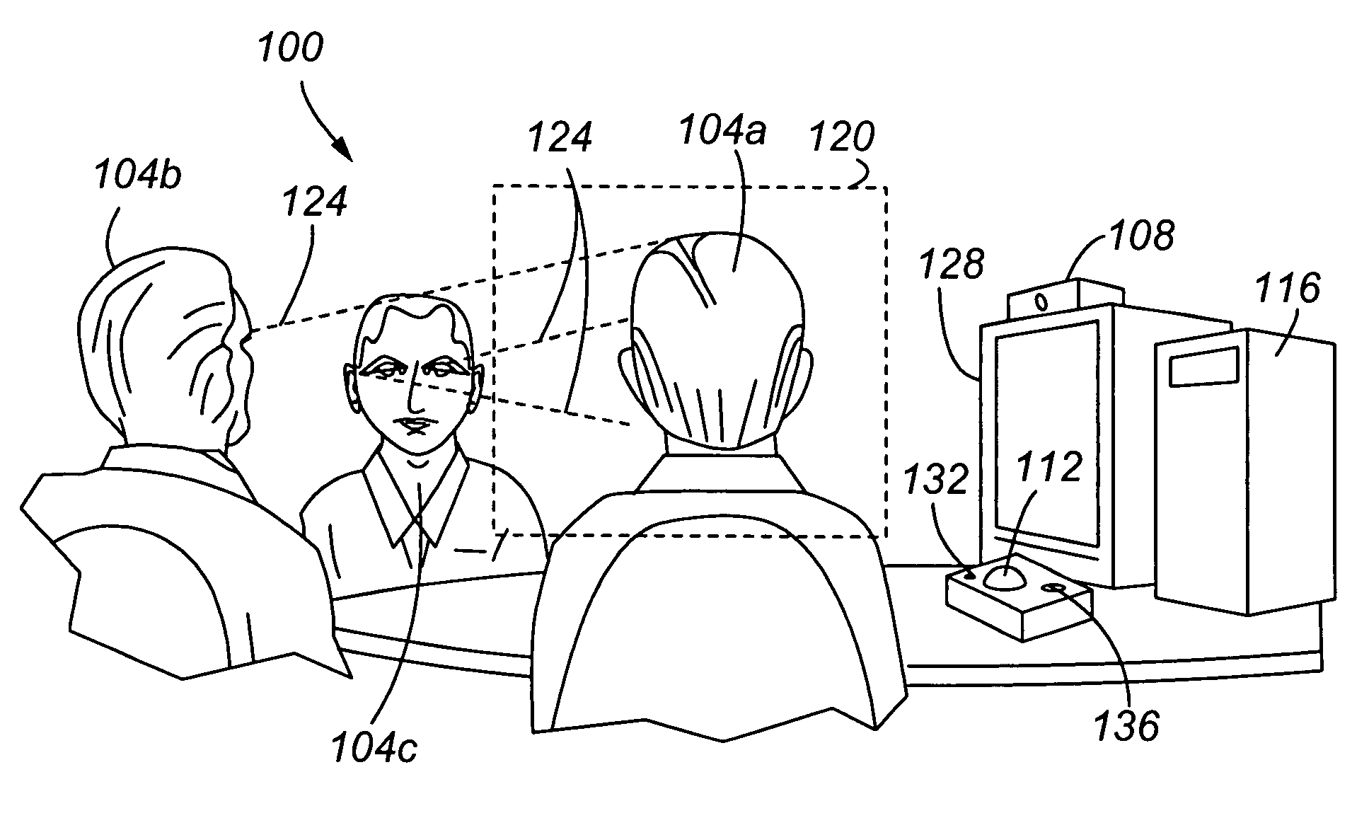
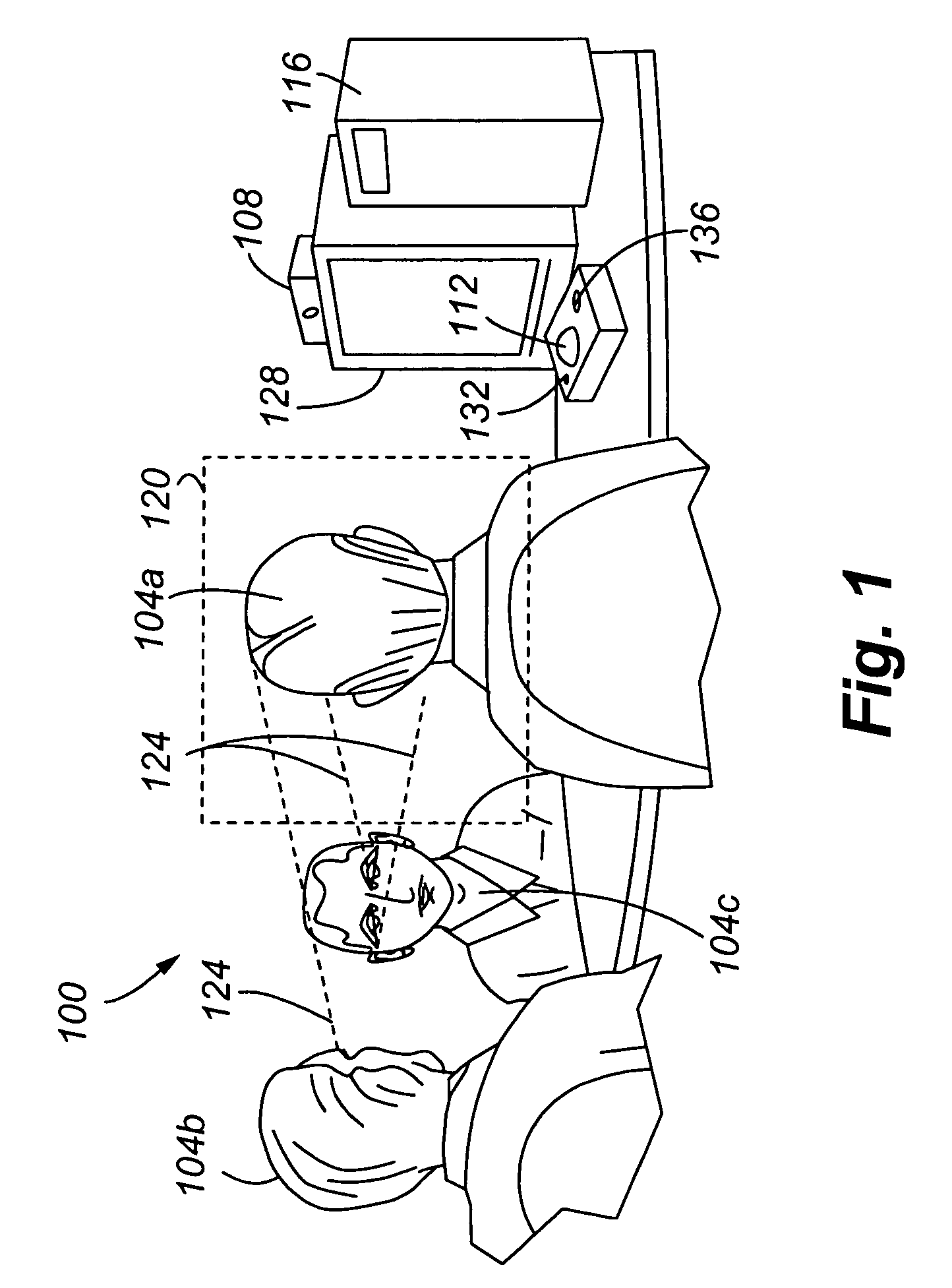
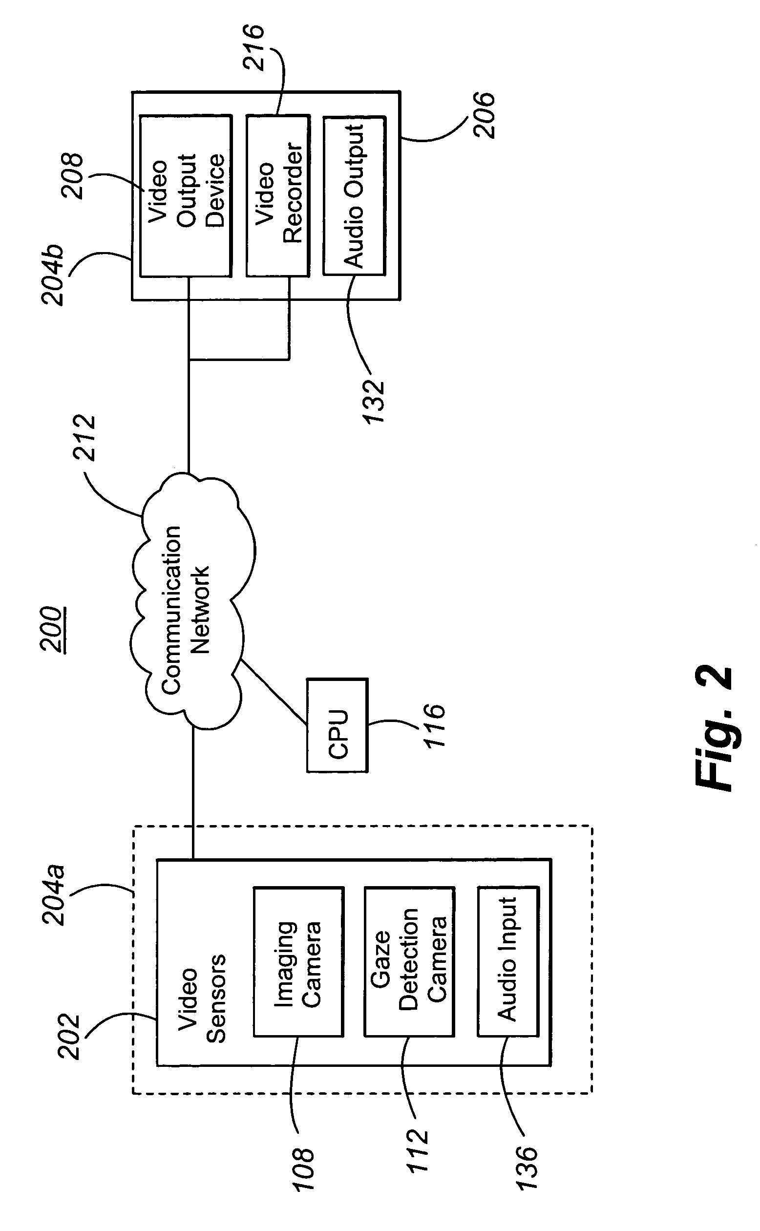
[0016]With reference now to FIG. 1, an example of a scene from which video information can be obtained is illustrated. As can be appreciated by one of skill in the art after consideration of the present disclosure, example contexts of a system in accordance with embodiments of the present invention include video conferencing and video surveillance. In general, the scene is of or corresponds to a first location 100 at which a number of persons 104 may be located. In addition, the first location generally includes components of a video endpoint 204 (see FIG. 2) or 304 (see FIG. 3), as will be described in greater detail elsewhere herein. Such components may include an imaging camera 108 and a gaze detection camera or device 112. The imaging camera 108 and gaze detection device 112 may further be associated with a central processing unit (CPU) 116.

[0017]In operation, the gaze detection device 112 obtains information regarding the direction of the gaze or line of sight of the various pe...


PUM


Abstract

Using gaze detection to determine image information collected from a scene. In order to determine the gaze of persons within a scene, images of the faces of those persons are obtained, and the gaze or line of sight of those persons is determined. Image information encompassing an area of the scene at which the gazes of persons at the scene are directed is then obtained. The obtained video information may be displayed in realtime, or recorded for later viewing.

Description

FIELD OF THE INVENTION[0001]The present invention is directed to using gaze detection to determine an area of interest within a scene. In particular, the line of sight or gaze of persons at a location is determined, and image information from an area indicated by the detected gaze is obtained.BACKGROUND OF THE INVENTION[0002]In order to control the image obtained by a camera, manual remote control systems for controlling the pan, zoom and other functions of a camera are available. Such systems can allow video conference participants at a first location to control the image that is provided to participants at a second video conference location. Alternatively or in addition, manual systems may allow video conference participants at a second location to control functions of the camera at the first video conference location. Accordingly, such systems require input from a user in order to provide appropriate image content. Furthermore, such systems can be difficult to operate from a remo...

Claims


Application Information

Patent Timeline
IPC IPC(8): H04N5/225H04N5/222H04N7/14
CPCH04N7/147H04N7/15H04N23/90
Inventor COUGHLAN, MARC WILLIAM JOSEPHFORBES, ALEXANDER QUENTINMICHAELIS, PAUL ROLLERRUNCIE, PETER D.SCHOLTE, ALEXANDER MARTINWARTA, RALPH
Owner AVAYA INC
Why Eureka
Try Eureka