Structure for securing insert to insert drill

A technology of inserting drill bits and inserts, which is applied to the parts of boring machines/drilling machines, drill repairing, twist drills, etc., and can solve problems such as the separation of inserts, changes in the concentricity of inserts and tool holders, etc.

Inactive Publication Date: 2005-05-18
YESTOOL CORP
View PDF0 Cites 31 Cited by
  • Summary
  • Abstract
  • Description
  • Claims
  • Application Information

AI Technical Summary

Problems solved by technology

If the user inserts the insert into the mounting groove by mistake or carelessness, that is, if the insert is inserted into the mounting groove in such a way that the inner end of the fastening screw does not come into contact with the inclined groove of the insert, Then during the drilling operation, the insert may accidentally come out of the mounting groove of the shank, or the concentricity of the insert and shank may change

Method used


Image

  • Structure for securing insert to insert drill
  • Structure for securing insert to insert drill
  • Structure for securing insert to insert drill

Examples


Embodiment Construction

[0022] Referring now to the drawings, wherein the same reference numerals are used throughout to designate the same or like parts.

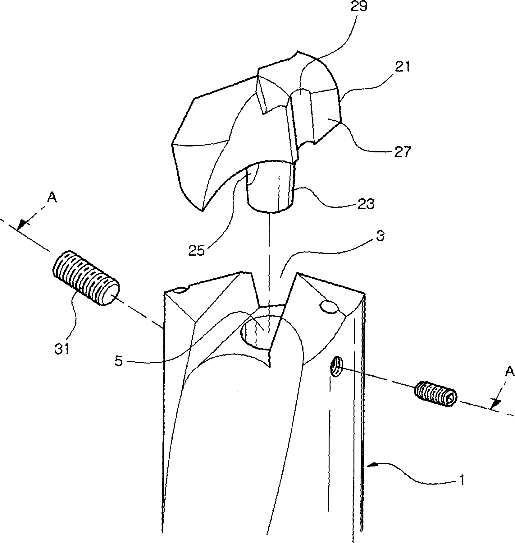
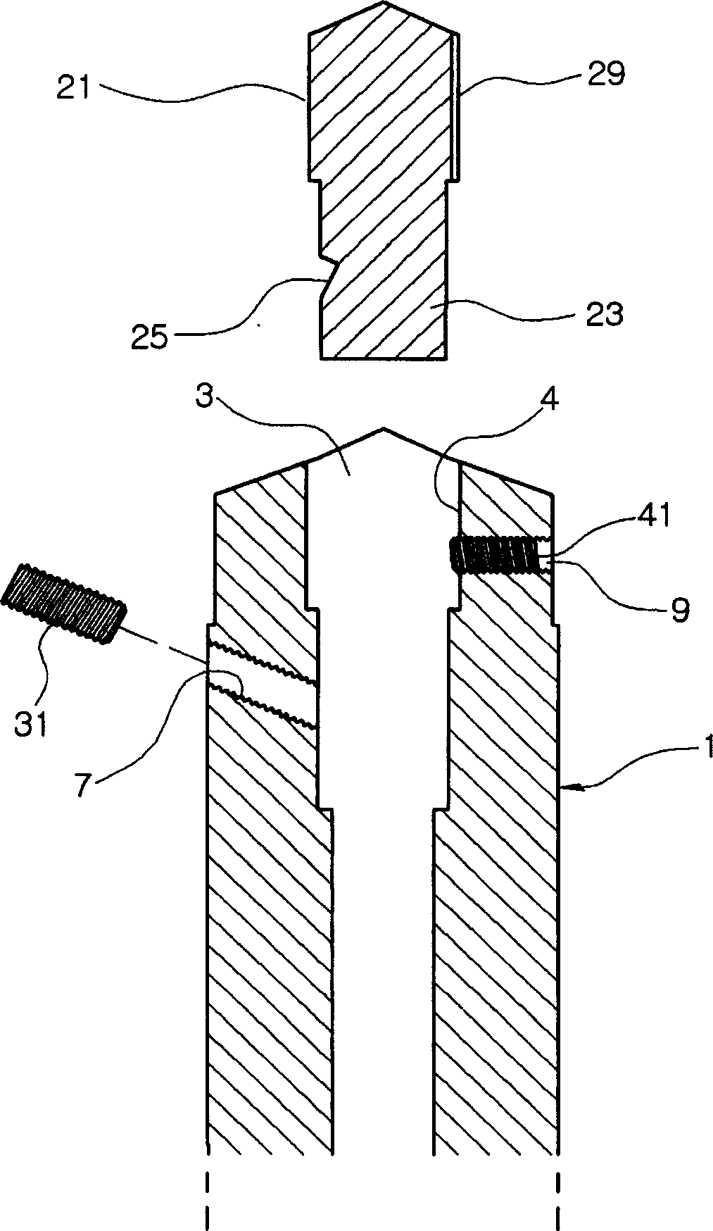
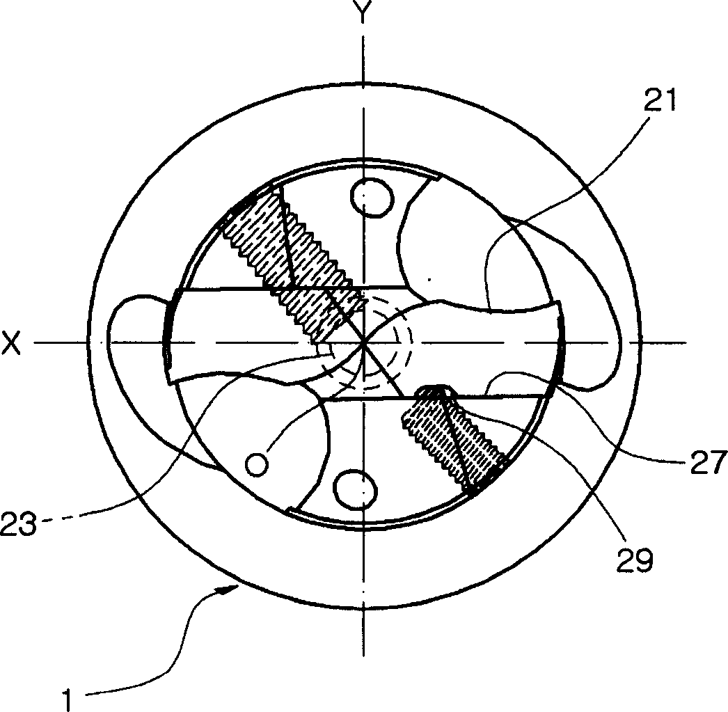
[0023] figure 1 is an exploded perspective view of the structure for fixing the insert 21 to the insert drill according to the first embodiment of the present invention. figure 2 is along figure 1 A cross-sectional view of the line A-A. image 3 yes figure 1 The top view of the insert fixing structure.

[0024] Such as figure 1 and 2As shown, the insert drill bit includes a tool holder 1 . Knife bar 1 has: the mounting groove 3 that is formed at one end of this knife bar 1; Knife shank hole 5, and it extends downward from the bottom wall of mounting groove 3 in knife bar 1; First screw hole 7, it is formed in this way in On a predetermined portion of the outer surface of the knife rod 1 , that is, extending to the knife handle hole 5 . The insert drill also includes an insert 21 inserted into the mounting groove 3 of the tool holder 1 . ...


PUM


Abstract

A structure for fixing an insert (21) to an insert drill, wherein the insert (21) is precisely arranged in a mounting groove (3) formed on one end of a cutter bar (1) of the insert drill. The insert drill bit comprises: a cutter bar (1) having a mounting groove (3), a handle hole (5), and a first threaded hole (7); an insert having a shank (23) and an inclined groove (25) (21); and the fastening screw (31). The insert fixing structure includes: a second threaded hole (41) formed on a predetermined part of the outer surface of the cutter bar (1), a guide groove (29) formed longitudinally on the joint surface of the insert (21), And the guide screw (41) that is screwed into the second threaded hole (9), the inner end of the guide screw (41) protrudes into the installation groove (3), so that when the insert (21) is inserted into the knife bar ( 1) When in the installation groove (3), the inner end of the guide screw (41) is accommodated in the guide groove (29).

Description

technical field [0001] The present invention generally relates to a structure for fixing an insert to an insert drill in which the insert can be precisely arranged at the end of a shank formed on the insert drill when the insert is inserted into a mounting groove In the installation groove of the cutter bar; the present invention particularly relates to such a structure for fixing the insert to the insert drill bit, in which the guide device is arranged in the installation groove of the tool shank, and the guide groove is formed in the insert and corresponding to the guide device, so that when the insert is inserted into the installation groove of the knife bar, the guide groove can be guided by the guide device, so that the insert can be accurately arranged in the installation groove of the knife bar Inside. Background technique [0002] In Korean Patent Application No. 2001-0014774 (filing date March 22, 2001) titled "Insert Drill Bit", the inventor of the present inventi...

Claims


Application Information

Patent Timeline
Patent Type & Authority Applications(China)
IPC IPC(8): B23B51/00B23B51/02B23B51/04
CPCB23B2251/02B23B51/02B23B51/0473
Inventor 李正洙
Owner YESTOOL CORP
Why Eureka
Try Eureka