Electric motor

A motor and insulating resin technology, applied in electric components, electrical components, electromechanical devices, etc., can solve problems such as insulation damage, and achieve the effects of high insulation endurance, reduced usage, and reduced manufacturing costs

Inactive Publication Date: 2005-06-15
FANUC LTD
View PDF0 Cites 11 Cited by
  • Summary
  • Abstract
  • Description
  • Claims
  • Application Information

AI Technical Summary

Problems solved by technology

image 3 As shown, the method of wrapping the coil 3 with the insulating paper 4 in advance and inserting it into the slot 2 is very likely to cause a cavity at the end 4a of the insulating paper 4, etc.
in addition, Figure 4 With the method shown, there is a high probability of creating a cavity 6 in the lower area (bottom side of the groove) of the insulating paper 4b forming the cover
In the case of using a motor in which the insulation between the coil 3 and the stator core 1 is made by this method, if a cavity is formed between the coil 3 and the stator core in the slot, electric charge will be concentrated in this part, which may cause insulation breakdown.

Method used


Image

  • Electric motor
  • Electric motor
  • Electric motor

Examples


Embodiment Construction

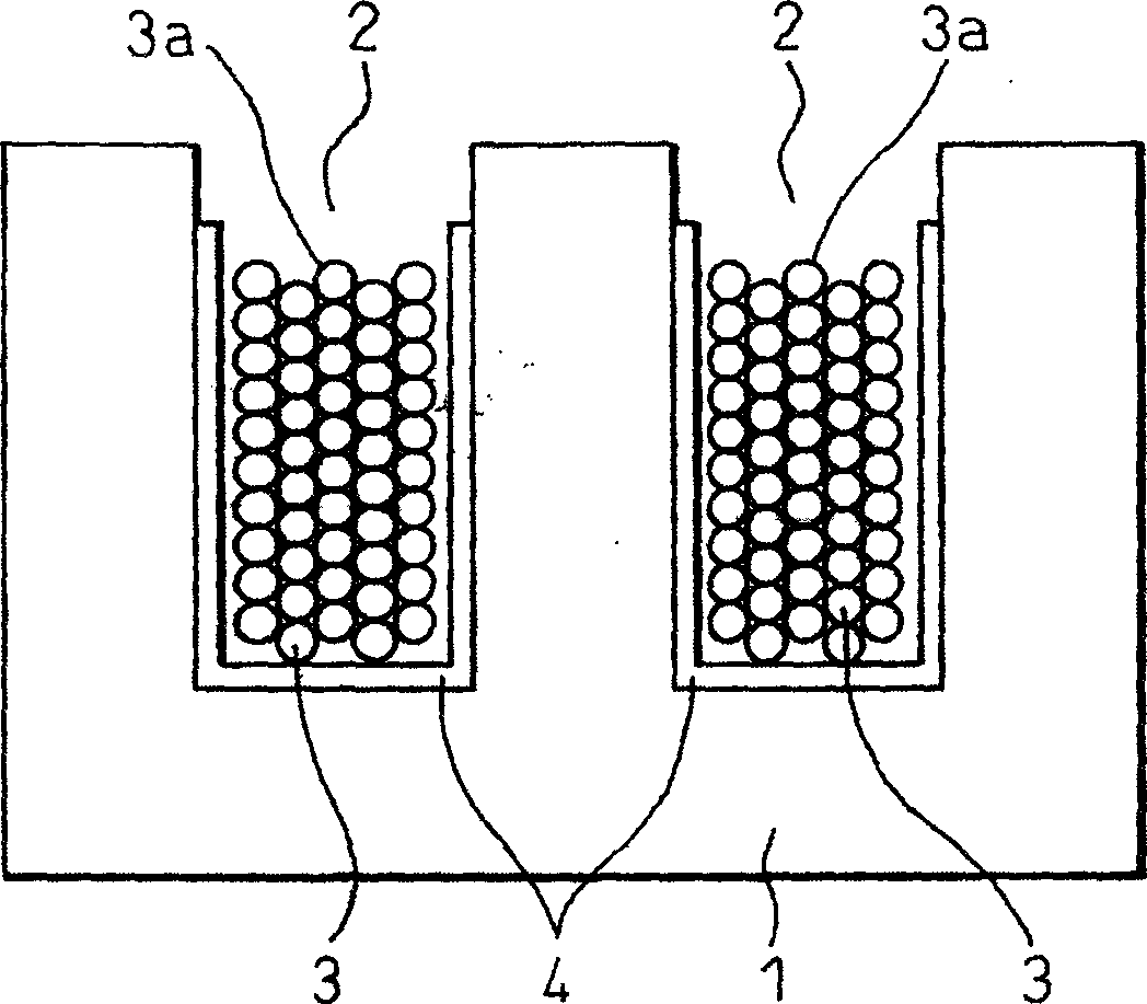
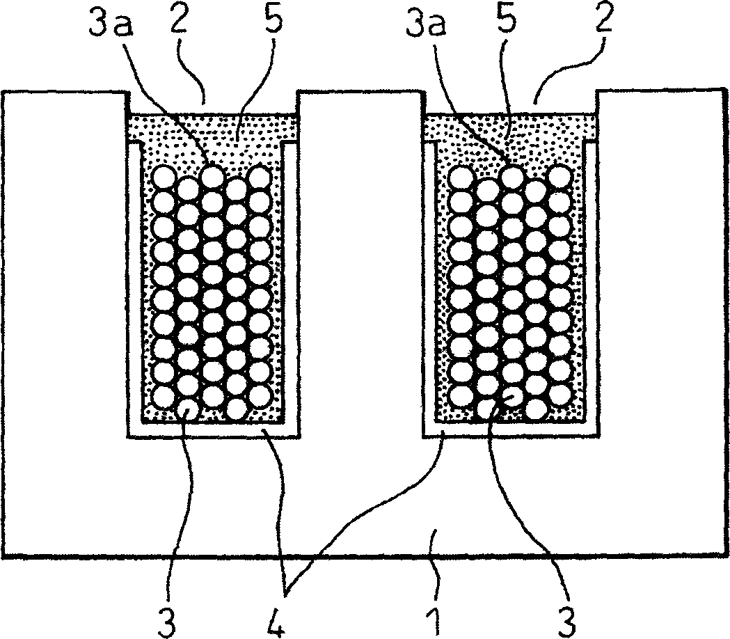
[0019] Figure 1a and Figure 1b It is an explanatory diagram of main parts of the first embodiment in which the present invention is applied to a linear motor. Figure 1a Indicates the state before molding with insulating resin, Figure 1b It shows the state after molding with insulating resin. Reference numeral 1 denotes a stator core, and reference numeral 2 denotes slots provided on the stator core 1 . In addition, reference numeral 3 represents a coil, and reference numeral 4 represents insulating paper. Additionally, for image 3 and Figure 4 The same components in the shown prior art examples are given the same symbols.

[0020] In each slot 2 of the stator core 1, the opening side of the slot 2 is reserved, and the coil 3 covered with the insulating paper 4 arranged along the inner surface shape of the slot is inserted into the slot 2 to form Figure 1a status shown in . Such as Figure 1b As shown, the coil 3 is not covered with insulating paper 4 on the open...


PUM


Abstract

The invention provides a motor, which has no or very few cavities in the slots of the stator core, so the insulation performance is high. The coil (3) is wrapped with insulating paper (4) opened to the opening side of the slot (2) of the stator core (1), and inserted into the slot (2). Then, molding is performed using an insulating resin (5). When the resin (5) is intruded into the groove (2), the air in the groove is discharged to the opening. Because there is no part to prevent the flow of the air, cavities such as cavities and holes can be prevented. The coil (3) can be insulated in the slot (2) in a state with very few cavities. Improved insulation resistance due to absence of cavities. In addition, manufacturing man-hours can be reduced, and the amount of insulating paper used can be reduced, so that a low-cost motor can be obtained.

Description

technical field [0001] The invention relates to the insulation of coils in stator core slots of electric motors. Background technique [0002] image 3 and Figure 4 It shows the insulation method of the coil in the stator core slot generally performed in the prior art. image 3 and Figure 4 The example shown shows an example of a stator core of a linear motor. image 3 In the example shown, the coil 3 inserted into the slot 2 of the stator core 1 is wrapped with insulating paper 4 in advance, and then the coil 3 wrapped with insulating paper 4 is inserted into the slot 2 of the stator core 1, and then used The insulating resin 5 is molded. In this case, a step is generated at the end portion 4 a of the insulating paper 4 , and a cavity (cavity) 6 that is not filled with the resin 5 may be generated in this portion. [0003] In addition, in Figure 4 In the example shown, the opening side of the slot 2 of the stator core 1 is left, the coil 3 is covered with insulating ...

Claims


Application Information

Patent Timeline
Patent Type & Authority Applications(China)
IPC IPC(8): H02K3/44H02K1/00H02K1/04H02K3/00H02K3/34
CPCH02K3/345
Inventor 曾我部正丰玉井孝幸
Owner FANUC LTD
Why Eureka
Try Eureka